By all accounts, my design for the 20MHz Low Cost Function Generator in the August 96 issue of Electronics Australia has proven very popular, with many thousands having been built. It's no wonder why, the low cost, simple construction and wide bandwidth made it a very attractive project. There was one major problem with the design however and that was the lack of a frequency display, and being able to set the frequency to exactly what you wanted. To this extent, one kit supplier in fact bundled the function generator with another frequency counter kit.
It's not surprising then that many people have asked for an updated design with a built in frequency display. Whilst a frequency display is easy to add, it adds significantly to the cost and complexity of the project. Also the analog nature of the design meant that temperature drift was also an issue.
This new design overcomes this problem, and adds a frequency display and digital frequency selection while still maintaining the low cost approach of the previous design.
The Design:
The design is based on a Direct Digital Synthesis (DDS) chip, the Analog Devices AD9835. It is a complete 50MHz (clock) sine wave generator on a single chip.
Going digital with DDS was the obvious decision, as the MAX038 used in the previous design is analog in nature and setting the exact output frequency is difficult unless you have many ranges with fine adjustment. Going digital allows you to set the output frequency exactly from 1Hz to 10MHz in 1Hz steps, and there is effectively no drift with temperature or time as the output frequency is crystal locked.
The AD9835 is clocked at 50MHz, so in theory it is capable of generating a sine wave up to 25MHz. At this frequency the output waveform quality is more difficult to control and amplify, so 10MHz was taken as the arbitrary upper limit, and this results in a good quality low distortion large output signal level over a 0 to 10MHz range. Whilst 10MHz is not as high as the 20MHz+ in the original design, it is still sufficient for most applications, and is beyond the 2MHz or so of most commercial analog bench generators.
Unfortunately, the AD9835 DDS chip is only available in a 16pin TSSOP (Thin Shrink Small Outline Package) surface mount package, which makes it challenging to solder by hand. A TSSOP package is half the pin pitch of your typical SOIC surface mount IC package, a mere 25thou (0.635mm). Compare it with the 74HC14 SO14 package also used in this design. More will be mentioned about how to solder this device later.
There are other DDS chips in the Analog Devices DDS product range with easier to handle packages, but they are much bigger, more expensive, and don't have a nice serial interface like the AD9835.
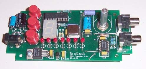
My first prototype for this design actually used an LCD display for the frequency readout, but this would have significantly increased the cost of the project. So I thought about it for a while and came to the realisation that you don't really need to display the entire frequency at any one time, it's nice but by no means essential. To display and set the frequency you really only need to display one digit at any one time, in which case a single 7 segment LED display can be used. In addition you need another indication which tells you what digit you are setting. The end result is a simple 7 segment LED display with a row of 3mm LED's to indicate which digit of the output frequency is being displayed and set. So the row of LED's correspond to X,XXX,XXX Hz. Our frequency display is now one tenth the cost of an LCD, and is easier to assemble.
To also help reduce the cost, the PCB has been designed to fit into a standard UB3 Jiffy box, with no wiring required, everything is PCB mounted. RCA output connector were chosen in preference to BNC connectors, as the PCB mount RCA connectors are about one tenth the cost of the BNC type. In fact, you can buy a PCB mount RCA connector and an RCA to BNC convertor for less than the cost of a BNC PCB mount connector.
A PIC16F628 8bit micro controller was chosen as the main controller. It has 2KB of internal FLASH program memory, 224 bytes of RAM, and 128bytes of EEPROM. This is adequate for our control program and data storage. This chip serves three purposes. One is to control the display and switches, the second is to send the necessary control commands to the AD9835 DDS chip, and the third is to store the output frequency in the internal EEPROM. The frequency set by the user is stored in the internal EEPROM and this same frequency is automatically set when the project is next powered up.
The 4MHz internal RC oscillator is used to lower system cost and to free the extra pins up for I/O functions. There are no critical absolute timing requirements in the project, so a crystal oscillator is not required.
How DDS Frequency Generation Works:
The internal block diagram of the AD9835 shows it's operation as well as that of a basic Direct Digital Synthesis (DDS) generator. A DDS generator consists of three major components - a phase accumulator, a sine wave lookup table (usually contained in ROM), and a digital to analog convertor (DAC).
The phase accumulator is also commonly refered to as a Numercial Control Oscillator (NCO), although no part of a DDS actually "oscillates".
As sine waves are non-linear in nature, they are not that easy to generate accurately, even using standard sampling techniques. The *phase* of a sine wave on the other hand is completely linear in nature, from 0 to 360 degrees, and thus lends itself to be more easily generated. Using a reference clock and the linear aspect of the phase, a DDS generator can generate very accurate sine waves of almost any frequency completely in the digital domain.
The phase accumulator basically performs an integration function and generates a linear phase "ramp" in proportion to the desired frequency, which is contained in the 32bit register FREQ0.
The sine (or cosine in the case of the AD9835) lookup table converts the linear phase ramp into a sine wave.
As sine waves are completely symetrical every 90 degrees, the lookup table only needs to store 1/4 of the waveform, with some appropriate control logic to map this over the full cycle. Different DDS devices have differing ways to do this however.
Even though the AD9835 contains a 32bit frequency control register, a 32bit (2^32 memory bits) lookup table is not required, as the AD9835 only has a 10bit DAC. So the (co)sine lookup table does not need to be much more accurate than this, in this case it's only 12bits. This ensures that the accuracy of the signal is determined entirely by the DAC resolution and linearity.
How it Works:
As you can see from the schematic there isn't much to the design. U3 does all the frequency generation, U2 handles the control and display, and U1 and U5 are provide output drive.
U3 is programmed by a custom three wire serial control bus from the micro controller U2. Data and commands are transferred in 16bit words. The serial interface is run asynchronously to the main clock, and can be run at any speed determined by the host micro controller.
U3 has various modes and internal registers that must be defined before it will output a frequency, and these are explained in the data sheet for those who are curious. U3 is also capable of frequency and phase modulation of the output signal, both of which can be controlled by either the serial bus or an external pin. For the sake of simplicity and cost reduction, these features have not been implemented into this design.
The actual output frequency is determined by the value in the 32bit FREQ0 register. The value in FREQ0 will be equal to F/(50MHz/2^32), where F is the desired output frequency.
From this equation you will see that with our 50MHz oscillator we can get approximately 12mHz resolution, and this value will also equal our output frequency uncertainty (ignoring crystal accuracy). In the case of a 1Hz output frequency, the FREQ0 register will contain the value 86 which equates to 1.001Hz, not quite 1Hz but close enough!
So at the low end of the frequency range the frequency accuracy will be 0.1% worst case, and at the high end the frequency accuracy can be controlled to a staggering one part in 4 billion.
Low distortion, like on the previous design was not a major design requirement, and so for simplicity, no measures were taken to improve this. The Total Harmonic Distortion is around the 1% mark, and this is adequate for most general applications. External output filtering can be added to improve this if desired.
U3 is clocked by U4, an industry standard 50MHz TTL/CMOS 8 pin DIP crystal oscillator. The stability of the generated output signal will be dependant upon this clock, but for this low cost application any grade oscillator will suffice. There are many brands of oscillator that match this standard footprint, some come in plastic DIP, while others come in a metal can package.
U3 requires digital and analog ground and power pins. These are individually decoupled at the at the power pins and run as separate lines from the regulators.
U3 provides a current output on pin 14, which is converted into a voltage by R4. C11 is an optional filter capacitor and is not fitted in the standard design. R2 sets the full scale DAC output signal current level, which in this case is approximately 3.9mA. This is already at a maximum value that will not compromise the performance of the chip. Thus the output voltage level across R4 will be approximately 1Vp-p referenced above ground, as U3 is only powered from a single power rail. This signal is AC coupled by C12 and referenced to ground and user adjusted by VR1. The signal is them amplified by a gain of 4.9, set by R5, R6. This gives an approximate maximum output signal level (at all frequencies) of +/-2.5V peak. Thus the final sine wave output level is adjustable from 0 to 5Vp-p. U1 provides a low impedance buffered output, and R7 provides a 50ohm output impedance. U1 can be either a National Semiconductor LM6361 or an Elantec EL2044. The EL2044 is the recommended device as it has a slightly higher bandwidth, and so will provide a higher signal level output at the high end of the frequency range.
U5 is a hex schmitt inverter, with C13,R1, and R3 providing a level shift function to bias the ground referenced sine wave input signal to half the supply rail suitable for a 5V TTL input. The schmitt input squares up the sine wave and provides a CMOS/TTL output.
The 7 segment display and digital LED's are multiplexed onto the same output pins on U2. The common cathode line for both displays goes back to a seperate pin on U2. U2 is thus able to "switch" alternately between displaying the 7 segment display and the digit LED's. This is done in firmware, and each display is turned on for a 5ms burst at a rate determined by the main loop. As long as it's greater than 50Hz or so you won't see any flicker, all the LED's appear to be continuously on.
The push buttons are debounced in the firmware by a small delay of a few hundred miliseconds after each key press.
The power supply is a typical half wave rectified AC input with positive and negative 5V regulators. Heat dissipation in the regulators will depend on the input voltage level from the plugpack, so ensure that this is not too high, a 9V AC plugpack is recommended as a maximum. The plugpack should be rated at 100mA or greater.
Parts Availability:
All of the components are readily available off the shelf for those who wish to construct the project from scratch. Farnell carry the "hard to get" bits like the AD9835, AD6361, 50MHz ocsillator, and surface mount 74HC14.
Whilst the TSSOP track/pad pitch is extremely small, it is not out of reach of home manufacture using good lithography techniques. It is however recommended that a proper solder masked PCB be obtained as this will make construction a lot easier.
The HEX file is available for download for non-comercial use from the SC website and the authors website at www.ozemail.com.au/~dljones
Short form kits and PCB's may also be available from the author.
Construction:
Start construction with the TSSOP package. This way there will be no other components to obstruct you, and the board will sit flat and steady on your bench.
Soldering the AD9835 is the most difficult aspect of project construction, and unless you have the right tools and experience it is likely that you will have problems. Don't underestimate how hard this will be, the pin pitch is 1/4 that of a regular IC, and half that of a standard SOIC. If you have a solder masked PCB then your job will be a lot easier, as the solder mask will help stop the solder bridging between pins. As a minimum you will need a good temperature controlled soldering iron with a fine tip suitable for surface mount soldering, 0.45mm solder and tweezers. A chiseled tip is much better than a conical tip which will have difficulty making good thermal contact. The ideal tip to use is the "wicking" chisel type which has a small cavity in the middle of the tip to help "wick" the solder back off the joint, this helps to keep the amount of solder on the pins to an absolute minimum.
Proper 0.45mm surface mount solder should be used, anything bigger will be a nightmare.
Alternatively if you have them available, proper surface mount solder paste and a hot air surface mount soldering gun will give you a first class job.
A magnifying lamp will come in very handy for this job, and many people will have to do the soldering under the magnifying lamp. You will need really good eyesight to solder and inspect the job without a magnifying lamp.
If you are using a regular iron and solder then the best approach is to apply a small amount of solder to one of the corner pads of the chip. Then use tweezers to place the chip over the pad (ensure correct orientation!) and heat up this one pin. You can then reheat this pad and move the chip around with the tweezers to get it properly centered. Before you solder any more pins, double check the orientation of the chip, as desoldering the chip later is an option you don't want to think about.
Once the chip is aligned on the pads correctly then solder the pin on the opposite corner so the chip will hold in place. A "wicking" motion of the soldering iron away perpendicular from the pin is your best shot at avoiding bridges between pins. The regular soldering technique of applying the iron to the pin and pad and then applying the solder on the other side of the joint will not work in this situation. The soldering iron tip and solder are both not small enough to allow this. You will find that excess solder will form around the joint no matter how hard you try to control how much you use. So you will have to just try and "wick" it away from the joint.
The biggest killer when hand soldering surface mount components is too much heat. Not only can excessive heat lift pads and crack tracks, but worse it can crack or destroy the component internally. Only solder one joint at a time and let the device cool before moving on. Do not apply heat to any joint for more than one or two seconds at most. Patience here will help prevent a big headache later.
The other 0805 passive components and the SOIC package are done next, and will be much easier to solder than the TSSOP, but similar rules apply. Watch the orientation of the SOIC.
Finish construction with the usual through hole components.
The PIC chip should be socketed to allow for firmware updates.
The 7 segment display will require a regular wide IC socket cut to size to stand it off from the PCB.
The LED's should be mounted about 10mm from the PCB. The easiest way to do this and to ensure alignment of al the LED's is to cut a 10mm strip of cardboard and place this between the legs of all the LED's while soldering. Watch the LED polarity.
The PCB is mounted behind the front panel by four 12mm spacers
You will notice on the prototype that R1, R3, and C13 are retrofitted on the underside of the board. The published design has these components added to the PCB as shown on the overlay.
Testing:
Before you power up the project, check for any shorts on the surface mount devices. Do a visual inspection and a multimeter check. Don't try and probe the pins of the TSSOP chip directly, instead probe the other end of the each track on a larger component.
Apply power to the project and measure the outputs of the regulators, they should be +/-5V. Ensure that the vital smoke does not escape from any of the components.
In Use:
When first powered up the project will most likely be set to 0Hz, so there will be no output waveform. This could vary though depending on the initial contents of the EEPROM bytes in the PIC chip.
In either case, press the SFT (SHIFT) button to select which digit will be displayed on the 7 segment display. Use of the SFT button allows you to quickly determine the output frequency.
The INC button will increment the currently display digit, and will wrap back to zero. There is no ability to decrement the number other than the wrap around.
Using SFT and INC does not update the frequency at the output, to do this you must push the SET button. This sets the output frequency and also stores the frequency in the internal EEPROM memory, so this frequency will be automatically reloaded when the project is next powered up.
Remember that the output frequency will only change when you press the SET button, so the display will only reflect the actual output frequency when you have not touched the INC button since the last time the output frequency was set.
When using the TTL/CMOS output, ensure that the output level control is set to maximum, as the this output generated directly from the amplified sine wave output.
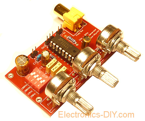
1Hz - 2MHz XR2206 Function Generator Kit
Function Generator is an essential laboratory equipment for every electronic. It allows a variety of measurements and experiments. The module described here is based on high quality XR2206 IC. 1Hz - 2MHz XR2206 Function Generator is capable of producing high quality sine, square and triangle waveforms of high-stability and accuracy. The output waveforms can be both amplitude and frequency modulated.
Purchase 1Hz - 2MHz XR2206 Function Generator Kit at
Electronics-DIY Store