| |
So, I needed a small transmitter, which would allow me to transmit good, old music into my AM-only radios. So, one saturday afternoon I got into gear, designed and built a very crude, terribly non-optimized little transmitter. It's almost a joke expressed in electronics, full of poor design, so please don't think that this is the best I can do! You must see it as a quick and dirty 5-hour effort, because that's all the time the transmitter took to design, build, and test. Making this web page about it is taking much longer! I'm putting this thing on the web only because many people have asked me to do so, despite its crude design!

If you have seen the antique radio section of my web site, then you know that I like restoring, and listening to, old radios from our grandfather's days. But these old radios receive AM only! FM had not yet gotten into common use. Today instead, the better sound quality offered by FM has driven AM stations almost completely out of the market in many places of the world. Where I live, during daytime I can still receive exactly three AM stations (this is in 2006), and that isn't much, considering that the AM broadcast band has room for more than 100 stations! At the same time, there are 31 FM stations... And what's worse, these three AM stations mostly transmit programming which doesn't suit my beautiful old radios at all! I mean, it's such a waste to have an Atwater Kent tube radio, in a nice polished wood cabinet, and let it blare out modern pop music, or today's news!
Here is the schematic diagram. You can click it to get a full resolution version, which is nice for printing. As you can see, the transmitter couldn't be much simpler: A TTL quartz oscillator provides a 1MHz square wave which is used to directly drive a transistor in full switching mode. A tank circuit turns the square wave into an approximate sine wave, and the 50 Ohm output is taken from one eleventh of the tank capacitive reactance.
The modulation part is equally bare-bones-simple: Two input jacks accommodate stereo signals, which are simply added to form the mono signal needed to modulate the transmitter. A trimpot allows to adjust the modulation level. Setting it to the middle of its range will provide correct modulation depth with a typical line level signal, as provided by most CD players. The audio adder drives a power transistor, which modulates the supply voltage to the RF transistor. That's pretty much all there is to it... Add a standard regulated 12V power supply, and an additional 6V regulator to bias the modulator and to power the TTL oscillator, and that's the whole circuit.
If this design had been made by someone else, I would find lots of things to criticize: The high values of the resistors in the audio circuit generate more noise than strictly necessary, but it's still low enough for this application. The audio bandwidth limitation given by C4 is not fixed, rather it varies with the setting of R4. Poor, but it works well enough in practice... Powering the 5V TTL circuit from 6V through a drop diode is pretty eclectic, but hey, it's cheap, it works, and allowed me to use one of those many 7806 chips I had lying around! The transistor I used for RF is really rated for UHF use, and using it at just 1MHz is a darn waste! But again, I have a stock of them, so I used it... And of course, starting with unregulated 20V, regulating down to 12V, then setting the bias point of the modulator at half that level, and then coupling the RF power transistor through a resistor, has the effect that the transmitter draws about 5 Watt from the AC line, while delivering only about 50mW RF output! That's 1% efficiency... But I won't criticize it at all, of course, since I made this thing!
I have certainly done better designs at other times. But it works well enough, so what! Here it is, and you are free to use it or skip it! :-)
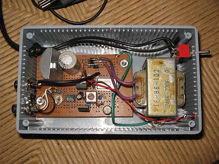
The transmitter is built into a plastic project box, and uses a piece of perfboard rather than a printed circuit board. Of course, a PCB would have been much more elegant, but designing and making one would have increased construction time by at least five times!
The RF transformer is actually a 455kHz IF transformer taken from a junked transistor radio from the 1970s. I removed its internal 470pF capacitor. With the external 100pF capacitor it can be easily tuned to 1MHz. It must have roughly 250 microhenry in the higher impedance winding, and the turns ratio of the low impedance one is about 1:10.
The 7812 regulator is mounted on a heat sink. The other parts don't need any heat sink, even if the 2SC1173 gets quite warm too.
I used RCA jacks for audio input and also for RF output. If you prefer, you can of course use other connectors. And a shielded box would be nice, but isn't really necessary. After all, you want this thing to radiate signals!
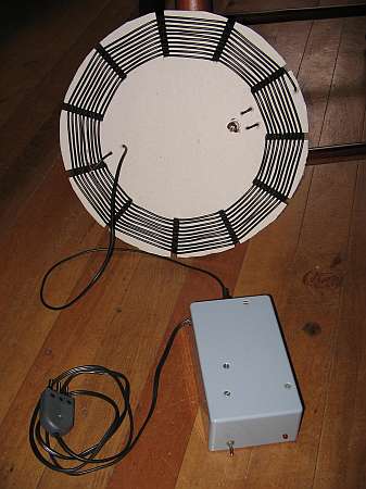
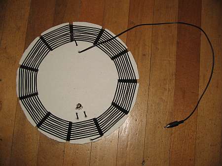
The antenna is a resonant multiturn loop. It has 19 turns of common household stranded wire, wound on a piece of strong cardboard that has 11 slits cut into its periphery. Why 11? Well, 10 or 12 sounds nicer, but we need an odd number, so that we can make the low parasitic capacitance winding! The wire changes sides of the cardboard through every slit, and to avoid having all turns touching each their neighboring ones, the number of slits must be odd.
The diameter of the cardboard disc is 30cm, and the slits are 5cm long. That makes the innermost turn have 20cm diameter, while the outermost one is about 28cm.
The coil is tuned by a nice old Philips air dielectric trimmer in parallel with a fixed capacitor. This capacitance connects between the coil's ends. The feed is installed over one turn, with the shield placed exactly at the middle of the coil (midpoint of the 10th turn), in order to get the best possible balance. The small coax cable (RG174, or plain audio shielded wire) is installed through holes punched in the cardboard, for stress relief. The trimmer is also installed through the board.
Tuning the system is simple: First you connect a load resistor of about 50 Ohm to the transmitter, and tune T2 for the highest signal. You can measure it with an oscilloscope, or with a simple RF probe and a multimeter. Then you connect the antenna, and tune its trimmer for maximum signal. Both sides of the trimmer are hot RF-wise, so use an insulated tool, or tune with your fingers in small increments and take your hand away in between to remove the detuning your hand introduces. You can measure the signal across the feed tap, or with a pickup look placed near to the antenna. When tuned, there will be about 5V on each turn, so a single turn placed near the antenna (10cm is near enough) will pick up about 5V of RF, which is easy to measure.
The natural Q of this antenna is above 300, so it would be much too high to allow a full 10kHz wide AM signal through! For that reason I fed the antenna over a whole turn. That dampens it down quite a lot, with the final overall Q ending up near 60. That's fine for getting enough bandwidth, while at the same time strongly suppressing the rather strong harmonics produced by the transmitter. The RF signal picked up from the antenna is very clean, while the signal of the transmitter into a dummy load is not clean at all.
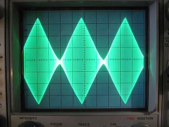
Here is a screenshot of the picked up signal, modulated by a triangle wave to the point where distortion sets in. Up to 80% modulation, the transmitter is highly linear. When going further up, though, the distortion becomes visible on the scope, and audible in the radio! I suggest setting R4 for 80% modulation on the highest audio peaks. You can do that using a scope, or you can do it by ear, adjusting R4 for a setting that provides modulation as high as possible without audible distortion.
The power radiated by this antenna is only a small portion of the 50mW the transmitter can provide. When tuned, the antenna's input impedance is much higher than 50 Ohm, resulting in a high mismatch to the transmitter. That's no problem at all, given that the transmitter is totally SWR-proof (thanks to R6), and considering that the purpose of this transmitter is just sending a signal into radios located in the same home! For that, you don't need more than a milliwatt or so of effective radiated power. This system does it nicely. At 6 meter distance between the transmitting antenna and a 1935 tube radio, the received signal is about as strong as the stronger two of the three local AM stations I can receive. Outside of my home, the signal quickly becomes undetectable.
A small hint: Before you consider copying this transmitter, make sure you don't have a local AM station transmitting at or near 1.000MHz! If there is one, you would have to find a quartz oscillator for a different frequency in the broadcast band, and that might be a lot harder than finding the 1MHz oscillator! In that case, it might be better to consider using a totally different drive source.
Related Links
Downloads
Small AM Transmitter - Link
|
|
|
| |
Accurate LC Meter
Build your own Accurate LC Meter (Capacitance Inductance Meter) and start making your own coils and inductors. This LC Meter allows to measure incredibly small inductances making it perfect tool for making all types of RF coils and inductors. LC Meter can measure inductances starting from 10nH - 1000nH, 1uH - 1000uH, 1mH - 100mH and capacitances from 0.1pF up to 900nF. The circuit includes an auto ranging as well as reset switch and produces very accurate and stable readings. |
|
PIC Volt Ampere Meter
Volt Ampere Meter measures voltage of 0-70V or 0-500V with 100mV resolution and current consumption 0-10A or more with 10mA resolution. The meter is a perfect addition to any power supply, battery chargers and other electronic projects where voltage and current must be monitored. The meter uses PIC16F876A microcontroller with 16x2 backlighted LCD. |
|
|
|
60MHz Frequency Meter / Counter
Frequency Meter / Counter measures frequency from 10Hz to 60MHz with 10Hz resolution. It is a very useful bench test equipment for testing and finding out the frequency of various devices with unknown frequency such as oscillators, radio receivers, transmitters, function generators, crystals, etc. |
|
1Hz - 2MHz XR2206 Function Generator
1Hz - 2MHz XR2206 Function Generator produces high quality sine, square and triangle waveforms of high-stability and accuracy. The output waveforms can be both amplitude and frequency modulated. Output of 1Hz - 2MHz XR2206 Function Generator can be connected directly to 60MHz Counter for setting precise frequency output. |
|
|
|
BA1404 HI-FI Stereo FM Transmitter
Be "On Air" with your own radio station! BA1404 HI-FI Stereo FM Transmitter broadcasts high quality stereo signal in 88MHz - 108MHz FM band. It can be connected to any type of stereo audio source such as iPod, Computer, Laptop, CD Player, Walkman, Television, Satellite Receiver, Tape Deck or other stereo system to transmit stereo sound with excellent clarity throughout your home, office, yard or camp ground. |
|
USB IO Board
USB IO Board is a tiny spectacular little development board / parallel port replacement featuring PIC18F2455/PIC18F2550 microcontroller. USB IO Board is compatible with Windows / Mac OSX / Linux computers. When attached to Windows IO board will show up as RS232 COM port. You can control 16 individual microcontroller I/O pins by sending simple serial commands. USB IO Board is self-powered by USB port and can provide up to 500mA for electronic projects. USB IO Board is breadboard compatible. |
|
|
|
|
ESR Meter / Capacitance / Inductance / Transistor Tester Kit
ESR Meter kit is an amazing multimeter that measures ESR values, capacitance (100pF - 20,000uF), inductance, resistance (0.1 Ohm - 20 MOhm), tests many different types of transistors such as NPN, PNP, FETs, MOSFETs, Thyristors, SCRs, Triacs and many types of diodes. It also analyzes transistor's characteristics such as voltage and gain. It is an irreplaceable tool for troubleshooting and repairing electronic equipment by determining performance and health of electrolytic capacitors. Unlike other ESR Meters that only measure ESR value this one measures capacitor's ESR value as well as its capacitance all at the same time. |
|
Audiophile Headphone Amplifier Kit
Audiophile headphone amplifier kit includes high quality audio grade components such as Burr Brown OPA2134 opamp, ALPS volume control potentiometer, Ti TLE2426 rail splitter, Ultra-Low ESR 220uF/25V Panasonic FM filtering capacitors, High quality WIMA input and decoupling capacitors and Vishay Dale resistors. 8-DIP machined IC socket allows to swap OPA2134 with many other dual opamp chips such as OPA2132, OPA2227, OPA2228, dual OPA132, OPA627, etc. Headphone amplifier is small enough to fit in Altoids tin box, and thanks to low power consumption may be supplied from a single 9V battery. |
|
|
|
|
|
Arduino Prototype Kit
Arduino Prototype is a spectacular development board fully compatible with Arduino Pro. It's breadboard compatible so it can be plugged into a breadboard for quick prototyping, and it has VCC & GND power pins available on both sides of PCB. It's small, power efficient, yet customizable through onboard 2 x 7 perfboard that can be used for connecting various sensors and connectors. Arduino Prototype uses all standard through-hole components for easy construction, two of which are hidden underneath IC socket. Board features 28-PIN DIP IC socket, user replaceable ATmega328 microcontroller flashed with Arduino bootloader, 16MHz crystal resonator and a reset switch. It has 14 digital input/output pins (0-13) of which 6 can be used as PWM outputs and 6 analog inputs (A0-A5). Arduino sketches are uploaded through any USB-Serial adapter connected to 6-PIN ICSP female header. Board is supplied by 2-5V voltage and may be powered by a battery such as Lithium Ion cell, two AA cells, external power supply or USB power adapter. |
|
200m 4-Channel 433MHz Wireless RF Remote Control
Having the ability to control various appliances inside or outside of your house wirelessly is a huge convenience, and can make your life much easier and fun. RF remote control provides long range of up to 200m / 650ft and can find many uses for controlling different devices, and it works even through the walls. You can control lights, fans, AC system, computer, printer, amplifier, robots, garage door, security systems, motor-driven curtains, motorized window blinds, door locks, sprinklers, motorized projection screens and anything else you can think of. |
|
|
|