| |
This Arduino can be used for old school prototyping as well. Just use it as a standard ATmega8 and program it with the ISP connector. And it is one of the cheapest Arduino boards, that you can get. Arduino is a great prototyping platform and most of you probably know already about it. If not, check out the Arduino pages and the Arduino playground and dive into it.
A couple of month ago I ordered my first Arduino board. It was one of the Diecimila revision. As I often try something on my breadboard, I found out, that it can get troublesome to connect the Arduino with the breadboard over and over again. Others found that out as well and have solutions for that. An Arduino clone that snaps nicely onto your breadboard, e.g. Boarduino or RBBB.
So what to do if these boards are far away across the ocean and it is holiday season everywhere? You may have guessed it, we build it on a prototype board.
Gather components
Luckily I had most needed components laying around. The ATmega168 is replaced by an ATmega8 but that is not a problem as the very first Arduinos were based on that chip.
ATmega8, 16MHz, 8kB flash memory, 1kB sram memory
2 x 0.1u capacitors
2 x 22p capacitors
16MHz crystal
10k resistor
1k resistor
red 3mm LED
button
6 pin header for ISP
3 pin header for serial communication
prototyping board
USBtoRS232 converter
ISP programmer
All components can be bought for about 4.50€, without the ISP programmer and the USBtoRS232 converter.
If I had a resonator, I would have taken that, instead of the crystal and the capacitors as it needs less space on the prototype board.
The USB to RS232 converter is called USB-2-bot and comes from another project. Any other converter would work as well, e.g. this USB-TTL-232-cable.
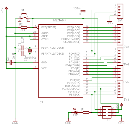
Schematic
The schematic is mostly the same as for the Boarduino. I left out the power supply circuit.
It has an ISP connector to program the bootloader and a serial connection used for uploading Arduino sketches. Also in place is a capacitor for the auto-reset function. It is connected to RTS line on pin 1 of the serial connection. The board should be feature compatible with Arduino.
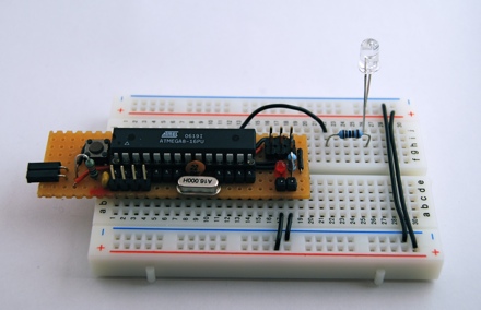
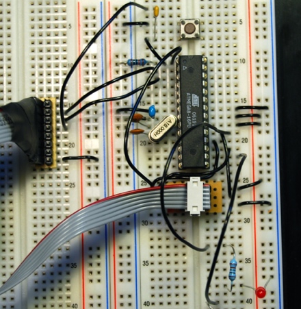
On a breadboard
First you can assemble all parts on a breadboard.
Bootloader
All Arduinos are comming with an installed bootloader. If you build it yourself, you have to program the chip with a bootloader, at least once. That is why we need the ISP programmer.
First I tried to use the ADABOOT bootloader which is a modified version of the original bootloader. It has some modifications that makes it more comfortable, e.g. starts your sketch right after the upload is finished, without having to wait several seconds. Unfortunately I could not get it to work. I was able to compile it after adding some special #defines for the ATmega8. Programming it worked as well. I can see that the bootloader runs, as it blinks the LED four times, but it wont connect to the Arduino IDE. It always gets a read timeout.
So I took the bootloader that came with the Arduino IDE. It can be found at /arduino-0010/hardware/bootloaders/atmega8/ATmegaBOOT.c.
You can try to call make to compile the bootloader or take the precompiled ATmegaBOOT.hex file. I needed to adapt the DIRAVR path setting in the Makefile to make it work. I used only the compile target, so I just typed
make clean; make
That gives you a warning, that delay.h has been moved, but you can ignore that.
Fuses
Next thing is to get the fuses right. If you are new to AVR microcontrollers, these fuses
are used to configure some properties of the AVR chip, e.g. which clock to use: an
external crystal or the internal oscillator. These fuses are registers that can be programmed, just as you can program flash memory.
Programming the fuses is always fun. Every option you want to enable or disable is represented as a bit and grouped in two 8 bit values, high fuse and low fuse (for ATmega8). To make it hard to read, programmed bits are represented by zeros and unprogrammed by ones. To make it more fun, if you mix things up, you can “brick” your controller and it can get hard to revive it. And because you probably do fuse programming only once per chip, you may have forgotten most of it when you have to do it again.
Good for us, that fuse bits are provided in the Makefile that comes with the bootloader. As I use avrdude for programming, this is how my command line looks like.
avrdude -v -c usbtiny -p ATmega8 -C /Users/alex/etc/avrdude-tiny.conf -U hfuse:w:0xCA:m -U lfuse:w:0xDF:m -U lock:w:0xFF:m
This writes the high and low fuses and the lock bits. Lock bits have to be written to enable programming the bootloader.
Programming
Now we are ready to program the bootloader.
avrdude -v -u -p ATmega8 -c usbtiny -C /Users/alex/etc/avrdude-tiny.conf -U
flash:w:ATmegaBOOT.hex
When that is done, try to hit the reset button and you should see the LED at pin 13 blinking. That signals that the Arduino is ready to accept your sketch.
Testing it with an Arduino sketch
Next thing is to check if our Arduino wants to speak to the Arduino IDE.
Start your Arduino IDE and load the Blink sketch from the examples. Compile/verify it and hit the upload button.
By now, and if everything goes well, you should see the LEDs of your serial connection blinking, resetting the Arduino and the uploading the sketch.
Then your LED connected to pin 13 will blink once every two seconds.
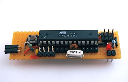
On the prototype board
If you have tested your components and your software successfully, you can move on to solder it on a prototype board.
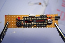
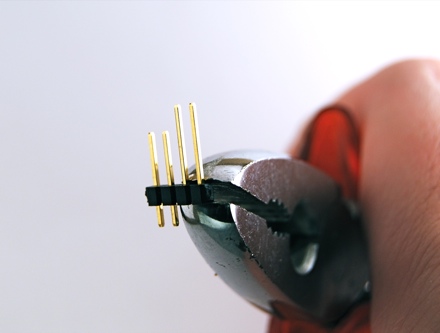
If you solder header connectors to a prototype board and try then to connect it to the breadboard, you will notice, that the header connectors are a bit short. I used my pliers to push the pins a bit. If you solder these, you will have a better connection to the breadboard.
Related Links
Downloads
Arduino Breadboard Clone - Link
|
|
|
| |
Accurate LC Meter
Build your own Accurate LC Meter (Capacitance Inductance Meter) and start making your own coils and inductors. This LC Meter allows to measure incredibly small inductances making it perfect tool for making all types of RF coils and inductors. LC Meter can measure inductances starting from 10nH - 1000nH, 1uH - 1000uH, 1mH - 100mH and capacitances from 0.1pF up to 900nF. The circuit includes an auto ranging as well as reset switch and produces very accurate and stable readings. |
|
PIC Volt Ampere Meter
Volt Ampere Meter measures voltage of 0-70V or 0-500V with 100mV resolution and current consumption 0-10A or more with 10mA resolution. The meter is a perfect addition to any power supply, battery chargers and other electronic projects where voltage and current must be monitored. The meter uses PIC16F876A microcontroller with 16x2 backlighted LCD. |
|
|
|
60MHz Frequency Meter / Counter
Frequency Meter / Counter measures frequency from 10Hz to 60MHz with 10Hz resolution. It is a very useful bench test equipment for testing and finding out the frequency of various devices with unknown frequency such as oscillators, radio receivers, transmitters, function generators, crystals, etc. |
|
1Hz - 2MHz XR2206 Function Generator
1Hz - 2MHz XR2206 Function Generator produces high quality sine, square and triangle waveforms of high-stability and accuracy. The output waveforms can be both amplitude and frequency modulated. Output of 1Hz - 2MHz XR2206 Function Generator can be connected directly to 60MHz Counter for setting precise frequency output. |
|
|
|
BA1404 HI-FI Stereo FM Transmitter
Be "On Air" with your own radio station! BA1404 HI-FI Stereo FM Transmitter broadcasts high quality stereo signal in 88MHz - 108MHz FM band. It can be connected to any type of stereo audio source such as iPod, Computer, Laptop, CD Player, Walkman, Television, Satellite Receiver, Tape Deck or other stereo system to transmit stereo sound with excellent clarity throughout your home, office, yard or camp ground. |
|
USB IO Board
USB IO Board is a tiny spectacular little development board / parallel port replacement featuring PIC18F2455/PIC18F2550 microcontroller. USB IO Board is compatible with Windows / Mac OSX / Linux computers. When attached to Windows IO board will show up as RS232 COM port. You can control 16 individual microcontroller I/O pins by sending simple serial commands. USB IO Board is self-powered by USB port and can provide up to 500mA for electronic projects. USB IO Board is breadboard compatible. |
|
|
|
|
ESR Meter / Capacitance / Inductance / Transistor Tester Kit
ESR Meter kit is an amazing multimeter that measures ESR values, capacitance (100pF - 20,000uF), inductance, resistance (0.1 Ohm - 20 MOhm), tests many different types of transistors such as NPN, PNP, FETs, MOSFETs, Thyristors, SCRs, Triacs and many types of diodes. It also analyzes transistor's characteristics such as voltage and gain. It is an irreplaceable tool for troubleshooting and repairing electronic equipment by determining performance and health of electrolytic capacitors. Unlike other ESR Meters that only measure ESR value this one measures capacitor's ESR value as well as its capacitance all at the same time. |
|
Audiophile Headphone Amplifier Kit
Audiophile headphone amplifier kit includes high quality audio grade components such as Burr Brown OPA2134 opamp, ALPS volume control potentiometer, Ti TLE2426 rail splitter, Ultra-Low ESR 220uF/25V Panasonic FM filtering capacitors, High quality WIMA input and decoupling capacitors and Vishay Dale resistors. 8-DIP machined IC socket allows to swap OPA2134 with many other dual opamp chips such as OPA2132, OPA2227, OPA2228, dual OPA132, OPA627, etc. Headphone amplifier is small enough to fit in Altoids tin box, and thanks to low power consumption may be supplied from a single 9V battery. |
|
|
|
|
|
Arduino Prototype Kit
Arduino Prototype is a spectacular development board fully compatible with Arduino Pro. It's breadboard compatible so it can be plugged into a breadboard for quick prototyping, and it has VCC & GND power pins available on both sides of PCB. It's small, power efficient, yet customizable through onboard 2 x 7 perfboard that can be used for connecting various sensors and connectors. Arduino Prototype uses all standard through-hole components for easy construction, two of which are hidden underneath IC socket. Board features 28-PIN DIP IC socket, user replaceable ATmega328 microcontroller flashed with Arduino bootloader, 16MHz crystal resonator and a reset switch. It has 14 digital input/output pins (0-13) of which 6 can be used as PWM outputs and 6 analog inputs (A0-A5). Arduino sketches are uploaded through any USB-Serial adapter connected to 6-PIN ICSP female header. Board is supplied by 2-5V voltage and may be powered by a battery such as Lithium Ion cell, two AA cells, external power supply or USB power adapter. |
|
200m 4-Channel 433MHz Wireless RF Remote Control
Having the ability to control various appliances inside or outside of your house wirelessly is a huge convenience, and can make your life much easier and fun. RF remote control provides long range of up to 200m / 650ft and can find many uses for controlling different devices, and it works even through the walls. You can control lights, fans, AC system, computer, printer, amplifier, robots, garage door, security systems, motor-driven curtains, motorized window blinds, door locks, sprinklers, motorized projection screens and anything else you can think of. |
|
|
|