| |
The goal of this project is for me personally to learn a little more about fm transmitters and fm bug making (may the HAM radio gods bless me in this pursuit). The ideal outcome of this project is a very small and full functional FM transmitter that we can stick into a plastic mint box.
In order to be able to build this, we'll have to learn a lot about amplifiers, LC oscillators, mixers, antennas and FM. This project assumes you're already comfortable build your own PCB boards. If you're not please take a look at the homemade pcb's tutorial before you continue. It will help you out a lot.

So we've already seen mint can MP3 players and mint can amplifiers for guitars and tons of other projects, why not an FM bug transmitter? Well for starters, a tin can would be the worst place to put an fm transmitter! Luckily I stumbled upon this plastic mint box and thought...why not?
Two transistor FM transmitters and FM bug circuits are all over the internet and they all share a common design that will be followed in this project as well. The reason I'm not trying to invent something new here is simply because FM transmitters have been redesigned to death. Why not instead have some fun with it?
Parts
Electret Microphone
2x BC547 Transistors
2x 22nF Capacitor
1nF Capacitor
22pF Capacitor
2x 6p8 Capacitor
2.2uF Capacitor
10kΩ Resistor
22kΩ Resistor
1MΩ Resistor
47kΩ Resistor
470Ω Resistor
3v Button Battery CR2032
CR2032 Battery Holder
AWG 18 Wire
Breadboard Wire
PC Board
Solder
Soldering Iron
Power Drill
Plastic Mint Box
Parts List Details
For the most part, all of the parts used in this project are discrete and passive, with the exception of the transistors, which are the only real 'active' part of the circuit. The rest are just resistors, capacitors and inductors. Below I've described the most important parts for the project.
BC547 Transistor
These are tried and true HAM radio transistors, use them for this project. I would not substitute any other general use transistors like 2n2222 or 2n3904 when building this one, simply because the BC547's work. Further more, they're not even expensive. Use them!
AWG 18 Wire
This is standard copper wire, we'll be using it to make the RF coil in the oscillator as well as for the antenna. Be sure to get AWG 18 when buying it because the diameter does make a difference when building parts and making coils for this project.
6p8F Capacitor
Two of these capacitors are used in the oscilllator circuit. Again these are mission critical values unless you have an LC oscillator calculator infront of you, and you know what you're designing.
PC Board & Ferric Chloride
This circuit will not work on a breadboard, period. Don't even bother trying. You really need to use either perferoated board or a pc layout board like I'm going to use in this project. Copper Clad PC Board is relatively cheap and widely available just like ferric chloride, so don't skimp out, it's cheap and available use it!
Platic Mint Box
Please don't use a tin mint box, I can't stress this enough. The project will not work if it's inside of a metal box, there's just no way. So save yourself the hassle and (a) test the circuit out before putting it into the fm bug mint box and (b) don't use a metal mint box.
Schematic Overview
Here is the circuit for the FM Bug. In total there are 18 core components that are needed for the fm transmitter to work properly. The far left side has the electret microphone and then things move electrically to the right until they hit the antenna.
Schematic Specifics
•Electret Microphone
Don't let this microphone fool you, it's extremely sensitive albeit a bit clunky and big. You could shop around for a smaller microphone I'm sure but for this project, a standard electret microphone does the trick. The input is pulled high with a 22k resistor and passed to the amplifier circuit.
•Amplifier Circuit
The amplifier's job in this circuit is to take the audio input and beef up the voltage/current so that when it gets transmitted it travels further. More amplification means more higher fm transmitting power and longer range.
•Oscillator/Mixer Circuit
The last portion of the circuit with the 2nd BC547 is where the oscillator for the FM frequency is generated and mixed with the audio signal in order to form the frequency modulation used for FM radio. Don't worry, if all this is described a bit too quickly, the theory will be described more in depth in the next section.
Frequency Modulation
Since the FM radio band (88 to 108 MHz) will be used for FM transmitting in this project, we must first understand what the FM means, how it works and how we use it. Frequency Modulation (FM) transmits at a certain frequency, 107.9 MHz for example, and depending upon the audio signal input, the transmitted signal will have a fast frequency (for large positive voltages) or a slower frequency (for large negative voltages). The animation below best illustrates how the signal transmitted by the FM Bug will look.
You can think of the 'Signal' as what comes out of a microphone when you speak into it and the 'FM signal' as what goes out of the Antenna.
Creating FM Signals
What is so unique about this type of modulation is that, as long as we use a voltage controlled oscillator for creating the carrier frequency (i.e. 107.9 MHz), we just mix the amplified audio signal with that 107.9 MHz carrier and presto the newly created signal is frequency modulated, aka FM. If you look closely at the schematic below you'll see the exact point where this mixing/modulating occurs and the new FM signal is born.
The Common Emitter Amplifier
Aside from acting as on/off switches, transistors can also be used as amplifiers. Whole ranges of different transistors exist for different types of amplification. The Common-Emitter Amplifier (CE Amp for short), is probably the most common type of amplifier seen in standard electronics. The basic idea at work for amplifier used in the FM Bug is that the 1 Megaohm resistor biases the transistor in a way that when the Audio input goes into the base pin of the BC547 it is multiplied to be many times larger by the time it hits the Collector point of the transistor. Try using different resistance values other than 1 Megaohm and you'll see differences in the amplification factor.
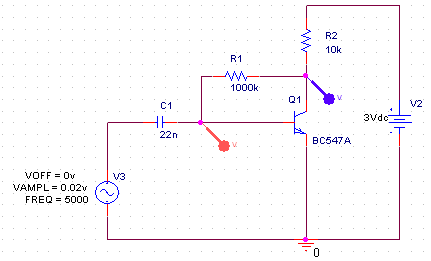
Simulating The Simple CE Amplifier
Spice is used here to simulate the amplifier circuit seen in the schematic for the FM transmitter in this project. Above I've already drawn out the amplifier portion of the circuit using Spice. The two points of interest are [1] where the red probe is, which is the filtered audio input and [2] where the purple probe is, which is the amplified signal coming out of the transistor.
FM Bug Amplifier Simulation Results
The audio input, a simluated sin wave at 5000 KHz shows up at about 50 milivolts peak to peak (red line graph). This is tiny, but about how much voltage the electret microphone puts out with the design seen in the schematic.
The purple line graph shows the amplified signal coming out of the transistor. The signal is about 1.2 volts peak to peak which is over 50x larger than the input signal. Clearly the signal has been amplified to a much larger value than it was at before.
The LC Oscillator Is A Tank Circuit
It was discovered pretty early on in electronics that if you put an inductor and capacitor in parallel with each other, they will resonate at a specific frequency. Ideally charge flows back and forth between the 'top' and 'bottom' capacitor plates generating this resonant frequency (similar to how a pendulum swings back and forth). Because charge seems to get trapped in ths circuit it got the bizarre name of 'The Tank Circuit' which is very common throughout all electronics.
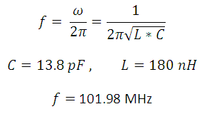
The LC Oscillator Formula
If we plug in the values seen above, the oscillator should create the correlating frequency and in an ideal world that is what happens. The big problem for us is we don't live in an ideal world and things like extra resistance and stray capacitance can effect the quality and frequency of the oscillator.
This means we need to keep parts close together to avoid large resistances and add a capacitor for feedback across the Common and Emitter pins of the transistor to keep the oscillator going. This type of oscillator is extremely sensitive and changes in other parts of a circuit can have an effect on the actual resonant frequency.
An LC Oscillator Simulation
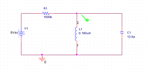
Spice is usually the tool of choice when simulating any electronic circuits. For this example I drew up a quick and dirty LC oscillator. The schematic can be seen below. This circuit would not be good for practical use because there is very little current flowing into the oscillator, but it does a good job of illustrating how the oscillator works.
The green probe looks at the voltage at that specific point over a period of time. In this case, since the expected frequency is 101.9 MHz, the period of the frequency will be around 10nS. The time range we'll look at is set to 60nS and the results can be seen below.
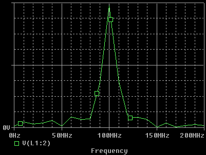
If you look closely you can see the period is just about 10nS as expected. But to triple check, I did an FFT on the signal which gave me the frequeny domain graph, which more obviously points out that the peak frequency generated by the circuit is around 101.9 MHz.
Now that we have a little more understanding of how the oscillator is made, how the audio signal is amplified and how the FM signal is created let's move forward and actually build this thing!
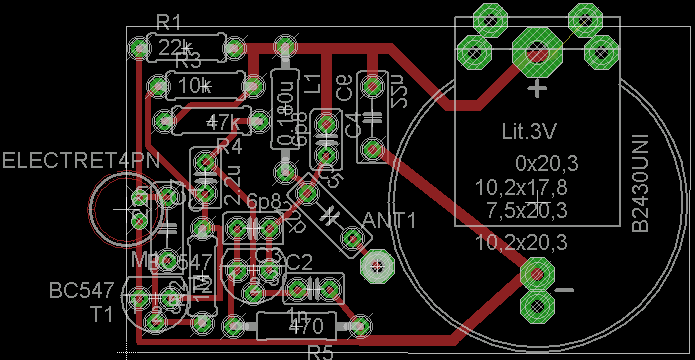
The PC Board Layout
Using Eagle Layout Editor, I entered in the fm bug schematic and then I laid the parts out on the smallest sized board I could. The final size of the board end up being about 4.5 by 2.6cm ~~ 1.7" by 1" for you non metric folk.
Making The PC Board
·Print out the layout on glossy paper, have the 5cm x 3cm copper board ready.
·Use a normal iron to apply heat to the glossy paper, transferring the toner.
·Toner transfer done. Use a felt pen to touch up any missing traces.
·Etch the board using ferric chloride to eat the copper.
·Etching is done, use a sponge to wipe off the toner.
·Drill the holes for the parts and you're ready to assemble it together!
Assembling The Board
Using the parts from the schematic and a soldering iron start soldering all the parts to the board. Everything but the antenna and the RF coil for starters.
·All the parts needed for assembling the FM transmitter. Solder them In!
·After you have soldered all the parts except for the RF coil and the Antenna, make the RF coil by wrapping the AWG 22 wire (14cm) around a small #2 screwdriver. The diameter of the coil should be around 5mm.
·Wrap it around the screwdriver loosely first.
·Squeeze the coil close and then solder it into the FM Bug PCB.
·At this point your board should be complete except for the Antenna.
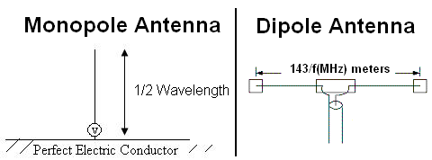
Making The Antenna
An size antenna will technically work for the transmitter, but some will be better than others. An ideal antenna would be 1/4 or 1/2 the wavelength of the transmitting frequency. 1/2 The wave length would mean an antenna of about 160cm, 1/4 a wave length antenna would be around 80cm.
The two types of antennas generally used with FM would be the monopole (sometimes called whip antenna) and the dipole. Ideally you want the wire to be 1/4 or 1/2 the wavelength of the frequency (i.e. 107.9 MHz). With proper design and some more parts we could make a tiny whip antenna, but I'll try my luck with a long coiled antenna....
May The Ham Radio Gods Forgive Me!
·Take a length of wire 80cm long and coil that bad boy up so that it can fit into the tiny mint box. Typically with monopole antennas you only want to coild them if they're shorter than 1/4 wavelength, but we'll see how things go later.
Fitting The FM Bug Into The Mint Box
Before you actually put the FM transmitter Bug into the mint box, you'll probably want to test it out to make sure it actually works. You might have to play around with the RF coil a little bit before a clear signal comes through.
·So here's the space we have for the transmitter...not much.
·Drill a small hole in the side for the microphone to fit into.
·The microphone isn't that obvious....is it?
·Get some tissue paper and cover up the electronics.
·Can't see the electronics anymore, put the lid on!
·Lastly, put the mints in and you're ready to go!
Data & Observations
So, there's no on/off switch and not wanting to be bugged in my own apartment I tested the circuit out first by blasting some music from my laptop into the microphone and then turned on my clock radio 25 feet away in the bathroom to get reception. The sound quality is 6 out of 10, but FM radio quality is never all that great to begin with.
Apologies in advanced for picking the most annoying german techno song for the demonstration video.
Originally I had an awesome video of some undercover operations with the bug, but I ended up getting in a little trouble, so hopefully the video you just saw is proof enough this system works. Sorry guys...I'm just too much of a trouble maker I guess 0=D.
An Overview Of The FM Bug Transmitter
The FM Bug transmitter is meant to be something fun that anyone can build given enough time and effort. The actual quality of the transmitter is not very good as you saw in the video, but it works up to 100 feet away and you can understand what comes out the other end. The build process was a little more tedious than usual, but there was no software to develop so things weren't all that bad.
What To Do Now
There's miles upon miles of things you can do to make this project better. The antenna could be improved, the board layout could be improved, you could add filtering on the output so you don't have a really wide bandwidth. You could even design a better amplifier so the signal travels farther. There's a lot of ways this project can be improved and used, so get to it and try to improve it!
Conclusion
The transmissions from the FM Bug transmitter weren't the clearest, but I'm moderately happy with how it came out. I was however, super bummed I couldn't include my undercover video...that's the whole point of the bug! Either way as a final disclaimer for you guys, don't do anything illegal with this and be sure to lookup in your respective countries what the allowable power transmissions are. So my real conclusion is, have fun with this bad boy but don't be one.


Related Links
Downloads
FM Transmitter Bug - Link
|
|
|
| |
Accurate LC Meter
Build your own Accurate LC Meter (Capacitance Inductance Meter) and start making your own coils and inductors. This LC Meter allows to measure incredibly small inductances making it perfect tool for making all types of RF coils and inductors. LC Meter can measure inductances starting from 10nH - 1000nH, 1uH - 1000uH, 1mH - 100mH and capacitances from 0.1pF up to 900nF. The circuit includes an auto ranging as well as reset switch and produces very accurate and stable readings. |
|
PIC Volt Ampere Meter
Volt Ampere Meter measures voltage of 0-70V or 0-500V with 100mV resolution and current consumption 0-10A or more with 10mA resolution. The meter is a perfect addition to any power supply, battery chargers and other electronic projects where voltage and current must be monitored. The meter uses PIC16F876A microcontroller with 16x2 backlighted LCD. |
|
|
|
60MHz Frequency Meter / Counter
Frequency Meter / Counter measures frequency from 10Hz to 60MHz with 10Hz resolution. It is a very useful bench test equipment for testing and finding out the frequency of various devices with unknown frequency such as oscillators, radio receivers, transmitters, function generators, crystals, etc. |
|
1Hz - 2MHz XR2206 Function Generator
1Hz - 2MHz XR2206 Function Generator produces high quality sine, square and triangle waveforms of high-stability and accuracy. The output waveforms can be both amplitude and frequency modulated. Output of 1Hz - 2MHz XR2206 Function Generator can be connected directly to 60MHz Counter for setting precise frequency output. |
|
|
|
BA1404 HI-FI Stereo FM Transmitter
Be "On Air" with your own radio station! BA1404 HI-FI Stereo FM Transmitter broadcasts high quality stereo signal in 88MHz - 108MHz FM band. It can be connected to any type of stereo audio source such as iPod, Computer, Laptop, CD Player, Walkman, Television, Satellite Receiver, Tape Deck or other stereo system to transmit stereo sound with excellent clarity throughout your home, office, yard or camp ground. |
|
USB IO Board
USB IO Board is a tiny spectacular little development board / parallel port replacement featuring PIC18F2455/PIC18F2550 microcontroller. USB IO Board is compatible with Windows / Mac OSX / Linux computers. When attached to Windows IO board will show up as RS232 COM port. You can control 16 individual microcontroller I/O pins by sending simple serial commands. USB IO Board is self-powered by USB port and can provide up to 500mA for electronic projects. USB IO Board is breadboard compatible. |
|
|
|
|
ESR Meter / Capacitance / Inductance / Transistor Tester Kit
ESR Meter kit is an amazing multimeter that measures ESR values, capacitance (100pF - 20,000uF), inductance, resistance (0.1 Ohm - 20 MOhm), tests many different types of transistors such as NPN, PNP, FETs, MOSFETs, Thyristors, SCRs, Triacs and many types of diodes. It also analyzes transistor's characteristics such as voltage and gain. It is an irreplaceable tool for troubleshooting and repairing electronic equipment by determining performance and health of electrolytic capacitors. Unlike other ESR Meters that only measure ESR value this one measures capacitor's ESR value as well as its capacitance all at the same time. |
|
Audiophile Headphone Amplifier Kit
Audiophile headphone amplifier kit includes high quality audio grade components such as Burr Brown OPA2134 opamp, ALPS volume control potentiometer, Ti TLE2426 rail splitter, Ultra-Low ESR 220uF/25V Panasonic FM filtering capacitors, High quality WIMA input and decoupling capacitors and Vishay Dale resistors. 8-DIP machined IC socket allows to swap OPA2134 with many other dual opamp chips such as OPA2132, OPA2227, OPA2228, dual OPA132, OPA627, etc. Headphone amplifier is small enough to fit in Altoids tin box, and thanks to low power consumption may be supplied from a single 9V battery. |
|
|
|
|
|
Arduino Prototype Kit
Arduino Prototype is a spectacular development board fully compatible with Arduino Pro. It's breadboard compatible so it can be plugged into a breadboard for quick prototyping, and it has VCC & GND power pins available on both sides of PCB. It's small, power efficient, yet customizable through onboard 2 x 7 perfboard that can be used for connecting various sensors and connectors. Arduino Prototype uses all standard through-hole components for easy construction, two of which are hidden underneath IC socket. Board features 28-PIN DIP IC socket, user replaceable ATmega328 microcontroller flashed with Arduino bootloader, 16MHz crystal resonator and a reset switch. It has 14 digital input/output pins (0-13) of which 6 can be used as PWM outputs and 6 analog inputs (A0-A5). Arduino sketches are uploaded through any USB-Serial adapter connected to 6-PIN ICSP female header. Board is supplied by 2-5V voltage and may be powered by a battery such as Lithium Ion cell, two AA cells, external power supply or USB power adapter. |
|
200m 4-Channel 433MHz Wireless RF Remote Control
Having the ability to control various appliances inside or outside of your house wirelessly is a huge convenience, and can make your life much easier and fun. RF remote control provides long range of up to 200m / 650ft and can find many uses for controlling different devices, and it works even through the walls. You can control lights, fans, AC system, computer, printer, amplifier, robots, garage door, security systems, motor-driven curtains, motorized window blinds, door locks, sprinklers, motorized projection screens and anything else you can think of. |
|
|
|


