| |
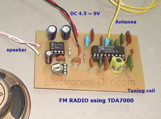
This project is a FM Radio based on TDA7000 and LM386 integrated circuits. What is unusual about TDA7000 IC is how it operates. It is a proper FM superhet receiver, with the usual local oscillator, mixer, IF amplifier, limiter, and phase detector. The difference is that there's only one tuned circuit; the local oscillator. Like the Pulse Counting Receiver, the TDA7000 relies on a low IF so that ordinary Op Amp circuitry can take care of the gain and bandpass characteristics. Only 70Kc/s is used with the TDA7000. Now, you might remember that the deviation of a broadcast FM signal is +/- 75Kc/s. A fully modulated signal would therefore sound rather distorted. So, how can this IC work?
It's quite simple in that there is what Philips call a Frequency Locked Loop. Basically, the local oscillator is shifted in response to detector output so that the bandwidth of the mixer output is never more than +/- 15Kc/s. It is actually compressing the frequency range of the modulated signal.
The muting or squelch feature is novel to say the least. Although it performs as any other muting circuit does, the TDA7000 provides an artificial noise generator so that the receiver still sounds alive while tuned off station. If you don't need that feature, just remove the .022uF condenser at pin 3. Not all Philips data sheets show it, but connecting a 10K resistor from the supply to pin 1 will disable the squelch.

Block diagram of the TDA7000 as used for a typical FM receiver. Audio output is around 75mv.
At this point I recommend you have a look at the Philips application notes. They give a good background to the design and use of this IC. For curiosity value, have a look here for the application notes regarding Narrow Band FM. In case you were thinking a low IF would be suitable for a NBFM receiver, you're right. Note that the TDA7000 is not suitable for feeding into a stereo decoder.
It is interesting to speculate as to why Philips didn't make this IC a pulse counting receiver. After all, the low IF is ideal, and pulse counting technology had been around for a while.
The TDA7000 starts a family!
Philips didn't stop with just the TDA7000 in its 18pin DIP package. Next came the TDA7010T which is the surface mount version. It comes in a 16pin SMD package. What of the other two pins? Well, the artificial noise generator has been dispensed with and so has the connection to one of the IF filter capacitors. The latter is a bit odd; I'm not sure if it could be dispensed with altogether or if they managed to fit it inside the chip. The data for both chips is the same apart from that.
Next comes the TDA7021T which is also surface mount but is stereo compatible. Lastly comes the surface mount TDA7088T which is mono only but has a search type tuning and works on 3V.
The TDA7000 is one of those IC's like the 555 that is a brilliant design with so many uses, but never really found its way into commercially made products. Instead it seems that it's kits and other homemade gear that have kept it going. I have never seen the TDA7010T or TDA7021T used in anything commercially made, or even a kit. The TDA7088T however does exist in some of those miniature keyring FM receivers that are popular of late.
R.I.P. TDA7000
Unfortunately as I write this in early 2004, the TDA7000 is no longer being produced having being withdrawn from manufacture, December 2003. Actually, it's a pretty long production run when you consider it is just over 20 years old. So, if you want to play around with this IC, keep in mind that there won't be any new stock. The last TDA7000's I bought a few months back were made in 1994, so I'd say there are ample stocks around for a while. Who knows; it might go the way of the ZN414 and be cloned by some other company.
However, all is not lost for the TDA7010T is electrically the same. It does mean you have to be able to make a PCB with tracks close enough together for surface mount. You could probably use it with existing PCB's by running fine wire to the pins, or even mounting the TDA7010T in an 18 pin header. This IC, the TDA7021T and TDA7088T are still current Philips production. The TDA7021T can also be used; you don't have to use it for a stereo receiver. And the TDA7088T can be used with a normal variable condenser if you want to. If you wish to avoid surface mount, there is another IC that works on the same principles; Sanyo's LA1800. This IC can drive headphones directly, and also includes an AM receiver section which is a simple TRF circuit, like the ZN414 or MK484.
Constructing a TDA7000 receiver
I bought my first TDA7000 IC in 1988 and tried to build up a receiver on a piece of matrix board. Here I learnt the first thing of importance. Layout and groundplanes are critical to using this IC. The Philips data gives a PCB layout and this should not be altered too much. Of course my matrix board receiver didn't work properly.
Bought from Tandy in Chatswood; like all their components, packaging was excessive. An abbreviated reprint of the Philips AN192 application notes was included.
Soon after, Electronics Australia did an article (June 1988) with a TDA7000 and LM386 for the audio. So, I purchased the PCB and constructed just the TDA7000 part. I didn't think much of the LM386 (and still don't) so I made a two transistor class A amplifier on another PCB instead. The other alteration was to use a BB809 varicap diode for tuning. I didn't like the idea of EA using a trimmer capacitor.
The receiver certainly worked but the "1.5uV" sensitivity seemed questionable. Also the way the squelch worked was a bit strange. Apart from that, the sound was very good.
Mains operated TDA7000 receiver
Around November 1990, I built my mains operated TDA7000 receiver. This used the EA PC board but fed a 6AV6 and 6DX8 amplifier in a plastic box. A 6X4 half wave rectified the mains with heaters powered off my original DSE2155 transformer. Of course being a live chassis set, precautions were taken. External screws were nylon, a mains rated transformer was used for the output transformer, and 400V isolating condensers were used to connect the aerial. A few years ago I removed the 6AV6 stage as the audio gain was much higher than needed. I had originally acquired the 5V supply for the TDA7000 and varicap diode from the 6DX8 pentode cathode. However, drift was a problem and found that the 6DX8 cathode current being only about 20mA was only just enough to power the 7805 regulator, leaving the TDA7000 barely functional. I simply half wave rectified the 6.3V heater supply to fix that one.
Very bland looking but functional. At left is the heater transformer, middle is the output transformer, and at the right is the PCB with the TDA7000. Note also the yellow ceramic aerial isolating condensers.
The Silicon Chip November 92 TDA7000 receiver
I built this receiver during 1995 and used it on the train for a few years. The circuit is very typical using an LM386 for the audio stage. The LM386 is a very noisy IC and I'm certainly not fond of it.
Originally I built it in a plastic box with speaker, but wanting to make it smaller, I built a new enclosure out of aluminium, with a lexan cover. (January 2004). I didn't bother including the speaker as I seldom used it. However, once I'd done this, the performance seemed very poor. Sensitivity was really bad. Eventually I noticed that it seemed like some sort of spurious oscillation was going on. Bridging the negative battery terminal straight to the case brought up a huge improvement, and a permanent cure was made by connecting the PCB groundplane to the chassis directly, not just relying on the headphone socket. It just goes to show how finicky things are at VHF.
I mounted 4xAA cells on the PCB where Silicon Chip intended the speaker to be placed. The squelch switch was not used; instead the squelch is permanently disabled. The telescopic aerial extends to 75cm which is a quarter wavelength.
Performance
How does it perform? For strong local stations it works very well, with excellent sound quality. Sensitivity is good...I would hesitate to agree with Philips claim of 1.5uV...more inclined to agree with Elektor's 7uV. I should mention that the Elektor article did include an RF amplifier which supposedly increased the sensitivity to .5uV.
The first notable limitation is the very wide capture range due to the AFC circuit. It's quoted as +/- 300Kc/s. That makes it impossible to receive weaker stations close in frequency to strong ones. For example, at home where I have 2ONE on 96.1Mc/s about 5 km away, I cannot receive 2WL on 96.5Mc/s which is about 90 km away. Nova on 96.9Mc/s from Sydney (50 km away) just makes it worse.
The worst feature by far is on weak signals. Instead of just being noisy, there is an awful disortion present. The super regen and pulse counting receivers are much easier to listen to on weak signals.
Tuning the receiver is critical, despite what Philips say in their application notes. It is actually better to have the squelch enabled when tuning as you will only hear a signal when the receiver is correctly tuned.
The mention of these limitations is in no way meant to be a negative criticism. All receivers eventually are limited in some way; I'm merely determining how the TDA7000 performs. The average listener is not going to use a receiver the same way I do. In this regard, the TDA7000 performs no worse than most commercially made portable FM radios. In fact it performs a lot better than some I have tried.
My recommendation is that you gear down the tuning control with a reduction drive, or use a pot with varicap diode. Leave the squelch enabled, or at least have a switch if you want to disable it. And don't expect it to perform as a Super DX receiver. As with all kinds of receiver, give it a decent aerial!
I highly recommend this IC for where non technical users are involved and where sound quality is important. For what it is, and the simplicity of use, it makes an excellent FM receiver.
PARTS LIST
IC1 : TDA7000 FM Radio IC
IC2 : LM386 Audio Power Amplifier IC
18-pin socket (for TDA7000)
8-pin socket (for LM386) Ceramic capacitors :
0.001 µF (#102 or 1n) x 1 pc
0.01 µF (#103 or 10n) x 1 pc
0.1 µF (#104 or 100n) x 4 pcs
0.0022 µF (#222 or 2n2) x 1 pc
0.0033 µF (#332 or 3n3) x 2 pcs
0.022 µF (#223 or 22n) x 1 pc
150 pF (#151 or 150) x 1 pc
180 pF (#181 or 180) x 2 pcs
220 pF (#221 or 220) x 2 pcs
330 pF (#331 or 330) x 2 pcs
Electrolytic capacitors : (10V min)
220µF or 470µF or 1000µF - x 2 pcs
4.7µF - X 1 pc
Preset
10K (or 20K or 22K) (trim pot)
C1 - Ceramic cap (see * schematic)
L1 - Adjustable coil for tuning broadcast stations
Resistors
10Ω 1/4W or 1/6W - x 1 pc
22K 1/4W or 1/6W - x 1 pc
Miscellaneous items :
2 ft wire (antenna)
8 Ohm dynamic speaker
9V battery snap
Related Links
Downloads
FM Radio with TDA7000 - Link
|
|
|
| |
Accurate LC Meter
Build your own Accurate LC Meter (Capacitance Inductance Meter) and start making your own coils and inductors. This LC Meter allows to measure incredibly small inductances making it perfect tool for making all types of RF coils and inductors. LC Meter can measure inductances starting from 10nH - 1000nH, 1uH - 1000uH, 1mH - 100mH and capacitances from 0.1pF up to 900nF. The circuit includes an auto ranging as well as reset switch and produces very accurate and stable readings. |
|
PIC Volt Ampere Meter
Volt Ampere Meter measures voltage of 0-70V or 0-500V with 100mV resolution and current consumption 0-10A or more with 10mA resolution. The meter is a perfect addition to any power supply, battery chargers and other electronic projects where voltage and current must be monitored. The meter uses PIC16F876A microcontroller with 16x2 backlighted LCD. |
|
|
|
60MHz Frequency Meter / Counter
Frequency Meter / Counter measures frequency from 10Hz to 60MHz with 10Hz resolution. It is a very useful bench test equipment for testing and finding out the frequency of various devices with unknown frequency such as oscillators, radio receivers, transmitters, function generators, crystals, etc. |
|
1Hz - 2MHz XR2206 Function Generator
1Hz - 2MHz XR2206 Function Generator produces high quality sine, square and triangle waveforms of high-stability and accuracy. The output waveforms can be both amplitude and frequency modulated. Output of 1Hz - 2MHz XR2206 Function Generator can be connected directly to 60MHz Counter for setting precise frequency output. |
|
|
|
BA1404 HI-FI Stereo FM Transmitter
Be "On Air" with your own radio station! BA1404 HI-FI Stereo FM Transmitter broadcasts high quality stereo signal in 88MHz - 108MHz FM band. It can be connected to any type of stereo audio source such as iPod, Computer, Laptop, CD Player, Walkman, Television, Satellite Receiver, Tape Deck or other stereo system to transmit stereo sound with excellent clarity throughout your home, office, yard or camp ground. |
|
USB IO Board
USB IO Board is a tiny spectacular little development board / parallel port replacement featuring PIC18F2455/PIC18F2550 microcontroller. USB IO Board is compatible with Windows / Mac OSX / Linux computers. When attached to Windows IO board will show up as RS232 COM port. You can control 16 individual microcontroller I/O pins by sending simple serial commands. USB IO Board is self-powered by USB port and can provide up to 500mA for electronic projects. USB IO Board is breadboard compatible. |
|
|
|
|
ESR Meter / Capacitance / Inductance / Transistor Tester Kit
ESR Meter kit is an amazing multimeter that measures ESR values, capacitance (100pF - 20,000uF), inductance, resistance (0.1 Ohm - 20 MOhm), tests many different types of transistors such as NPN, PNP, FETs, MOSFETs, Thyristors, SCRs, Triacs and many types of diodes. It also analyzes transistor's characteristics such as voltage and gain. It is an irreplaceable tool for troubleshooting and repairing electronic equipment by determining performance and health of electrolytic capacitors. Unlike other ESR Meters that only measure ESR value this one measures capacitor's ESR value as well as its capacitance all at the same time. |
|
Audiophile Headphone Amplifier Kit
Audiophile headphone amplifier kit includes high quality audio grade components such as Burr Brown OPA2134 opamp, ALPS volume control potentiometer, Ti TLE2426 rail splitter, Ultra-Low ESR 220uF/25V Panasonic FM filtering capacitors, High quality WIMA input and decoupling capacitors and Vishay Dale resistors. 8-DIP machined IC socket allows to swap OPA2134 with many other dual opamp chips such as OPA2132, OPA2227, OPA2228, dual OPA132, OPA627, etc. Headphone amplifier is small enough to fit in Altoids tin box, and thanks to low power consumption may be supplied from a single 9V battery. |
|
|
|
|
|
Arduino Prototype Kit
Arduino Prototype is a spectacular development board fully compatible with Arduino Pro. It's breadboard compatible so it can be plugged into a breadboard for quick prototyping, and it has VCC & GND power pins available on both sides of PCB. It's small, power efficient, yet customizable through onboard 2 x 7 perfboard that can be used for connecting various sensors and connectors. Arduino Prototype uses all standard through-hole components for easy construction, two of which are hidden underneath IC socket. Board features 28-PIN DIP IC socket, user replaceable ATmega328 microcontroller flashed with Arduino bootloader, 16MHz crystal resonator and a reset switch. It has 14 digital input/output pins (0-13) of which 6 can be used as PWM outputs and 6 analog inputs (A0-A5). Arduino sketches are uploaded through any USB-Serial adapter connected to 6-PIN ICSP female header. Board is supplied by 2-5V voltage and may be powered by a battery such as Lithium Ion cell, two AA cells, external power supply or USB power adapter. |
|
200m 4-Channel 433MHz Wireless RF Remote Control
Having the ability to control various appliances inside or outside of your house wirelessly is a huge convenience, and can make your life much easier and fun. RF remote control provides long range of up to 200m / 650ft and can find many uses for controlling different devices, and it works even through the walls. You can control lights, fans, AC system, computer, printer, amplifier, robots, garage door, security systems, motor-driven curtains, motorized window blinds, door locks, sprinklers, motorized projection screens and anything else you can think of. |
|
|
|