| |
The transmitters on my homepage seem to be quite popular, especially those intended for the 88 - 108MHz FM band. I must really confess that I also favor this broadcast band, mainly because it is so easy to find signals on the workshop radio. Everyone has an FM radio, and it is fun to play with. Experimental antennas and the like can all be developed in this band since there are a huge range of "beacons" all transmitting just for my benefit :-). Basic oscillators also are easy to fault-find in this frequency band, and then later modified for other VHF bands.
The V5 FM Wireless Microphone is a 10mW transmitter that featured a coil fabricated on the PCB itself. This made the project easy to duplicate and removed "microphony" (the ability of coils to act as a microphone with spring-line reverb). But as several people have already commented, although more stable than most other similar kits and projects, the frequency still does vary with battery voltage. In just one session it can vary by 200kHz when a cheap "Mighty Atom" battery falls to 8 volts.
The project described here was designed for a "LINE OUT" level from my stereo, or computer, so I can use those FM radio headphones/ear defenders in the workshop when drilling, or when I was out on the tractor. I thought to myself (I said it out loud, but who in their right mind will admit to speaking to oneself?), "Why not find solutions to a few of the other problems, too?"
The basic problems with the V5, as I saw them were:
Battery voltage / frequency stability
No immunity to supply voltage ripple
Amplitude modulation also present
No output level indication
Buffer stage untuned and provides no gain
TR1 biasing changes the oscillator conditions
TR1 gives too great sensitivity for LINE levels
Many constructors want a frequency control to twiddle
There are several more "faults" but I feel depressed enough, so I will just stop here. But in my mind the first three on the list are the important points to address. The only other item is that varicap (varactor) diodes are too expensive here in Sweden, so I had to design without them.
The Circuit
As you can see below, the circuit is basically conventional: it is an oscillator driving a tuned amplifier stage. There's no "rocket science" here! Just a good old two-transistor transmitter, with a bit of thought.
The new V9 transmitter
TR1 is the oscillator transistor, in a Pierce oscillator configuration, just the same as TR2 in the V5 transmitter. The base of the oscillator transistor is biased by a 5v regulator chip: a small 78L05 in a plastic case. This device is more stable than a zener diode, but a simple zener with a glass case is also light sensitive!!
Feedback is from collector to base, via a 2p7 capacitor, and the coil is etched on the PCB itself. Incidentally, you can add turns instead of the wire link, this will lower the frequency and can cover the 50MHz and 70MHz amateur bands. The coil is resonated by a 22pf preset to determine the oscillator frequency. The preset capacitor is in series with a 33pf NPO capacitor, to limit the maximum capacitance. This sets the frequency RANGE of the transmitter. The coil also has a 6.8pf capacitor fitted to set the lower frequency limit of the transmitter. This can be raised to 27pf to get to the lower VHF bands.
A small tapping of the PCB coil is fed via an 18p cap to TR2. TR2 is a "common base" amplifier. This configuration has better input-output isolation than a more usual common-emitter stage. It does mean that power is wasted in the emitter resistor, but TR2 does provide a good gain. The colector of TR2 is tuned in exactly the same way as the oscillator and the preset tuning capacitor, the trimmer and padder capacitors should be similar in value.
TR2 provides about 12dB of power gain, but the output level from TR1 (about 8mW) is attenuated to about 1.5mW at the input of TR2. This gives us about 40mW at the collector of TR2. A 50-Ohms level is taken off at 1.5 turns from the top of the collector tuning coil. As always, tuning is a problem. You normally need a power meter, or a spectrum analyser! Now you don't need anything. I have built in a simple diode detector that reads approximately 2v DC for 40mW output.
Modulation
Modulation has always been a problem. Some people want AM, or ON/OFF keying. Some people want FM only. I want FM without the AM content. This means that the traditional method of modulating the oscillator is right out. The base bias to TR1 is regulated, which even removes ripple from the supply voltage. It prevents TR1 being modulated with AM or FM. In addition to this, the 12v supply is fed through a 7809 1-Ampere regulator to remove ripple to all the transmitter stages. The 5v regulator therefore regulates from a regulated supply. Call it super-regulation, if you want. I used a 10-Ohm resistor instead of the wire link - nothing to loose, but unwanted RF.
Amplitude Modulation The suppply voltage to the buffer amplifier has been fed via a link. Remove the link and you can modulate the supply voltage to the amplifier to get AM. You can also feed this stage from the output of a complementary amplifier WITHOUT the usual speaker DC block capacitor. You can drive this transmitter nicely with an LM380 audio amplifier. The LM380 should be fed with a 12v (13.8v nominal) supply. For audio AM you should replace the 22nf and 10uf supply decoupling caps with a 1nf, and a 10nf. If you want AM for TV then use 47pf and 220pf, but the 220pf may need to be reduced if your modulator does not have a really low output impedance.
Frequency Modulation This is always a problem. I want no AM content, true FM, and I want an audio response from DC to 60kHz. This is so I can add a stereo encoder. I also want a sensitivity good enough for a high-output microphone. This means I need a varactor diode. A quick visit to Allt mellan antenn och jord, priser mellan himmel och helvette! (Everything between antenna and ground, prices between heaven and hell!) showed me the error of my ways - forget varicaps!. Rectifier diodes have a usable capacitance, BUT zener diodes are much, MUCH better. They have a good voltage capacitance range that can be misused, as long as the supply voltage does not exceed the avalanch point. So, I used a 16v 400mW diode. Paint it black or put it in a plastic tube, if the diode has a glass body, otherwise it will respond to light.
I can rob the +9v supply directly to feed the diode, via a 22K resistor because there is no power-supply ripple on the 9v supply, thanks to the 7809 regulator. The bottom of the diode is coupled to the wiper of a 10K pot and 150pf capacitor, thus making it an RF ground, BUT not ground for DC to a couple of MHz. The modulation characteristic of this transmitter extends well into the RF spectrum. This also means you can use it for experimenting with data transfer :-). Turn the pot down and you have NBFM.
Alignment
No-matter what you do, if you want power out then there will be power taken from the oscillator. This WILL have a small effect on the frequency, depending upon how much power you take. We can set the rough frequency with the preset capacitor in the oscillator stage. Now connect a DC voltmeter, with a sensitivity of better than 10k-Ohms per volt, to the test terminal. Adjust the preset cap for the amplifier for maximum voltage. Now go back and re-set the frequency preset for the final frequency you want.
If you monitored the transmitter on an analyser, you would see that as you tuned the amplifier stage from low-to-high, as the amplifier reached the resonance, the oscillator went up in frequency a small amount. When you go past resonance it increased a little and stayed there as you tuned up the rest of the band. This frequency "pulling" near resonance is the amplifiers effect on the oscillator. The total frequency variation is about 300kHz at 100MHz, but at 70MHz it was only about 25kHz.
Frequencies
Use a smaller coil in TR2 collector, and bridge a couple of inner turns of the oscillator coil and this transmitter will go up to about 170MHz. You will also have to remove the 6.8pf padders from both oscillator and amp. As a matter of interest, I used a particularly cheap zener diode. It's fixed capacitance was quite high, so the 6.8pf in the oscillator was reduced to 4.7pf. If you go up to 170MHz then you may need to reduce the 15pf from the tuning diode to as little as 4.7pf.
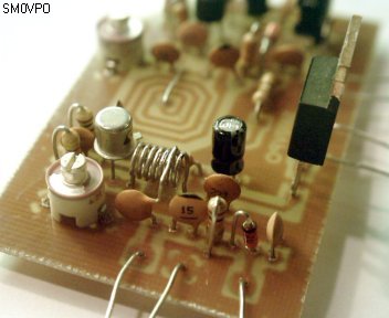
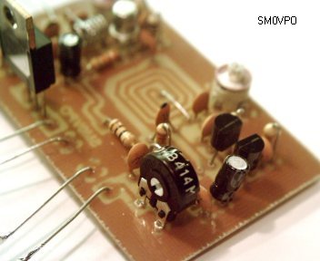
A good shot showing L2
For 100MHz the coil in the amplifier stage is 7 turns tinned-copper wire, wound on a 4mm drill bit. The turns space is about the thickness of my right thumb-nail. The diameter of the wire is about 0.5mm. For other frequencies you can simply scale the number of turns, and adjust the total tuning capacitance accordingly. If you want to solder to just one turn, then fold two bist of paper and place them either side of the loop to be soldered. Now you can put the capacitor wire on the coil and solder with ease :-)
Prototype
This transmitter was built on a single-sided printed circuit board, with loads of ground-copper. This makes it very frequency stable when handling the board. I used heat-breaks whenever possible, and all the components are standard and available almost anywhere. The only possible source of worry may be the two transistors. BC547 is common most places, and the 2N2369 can be replaces with any "small signal transistor" with an "ft" of 400MHz, or more.
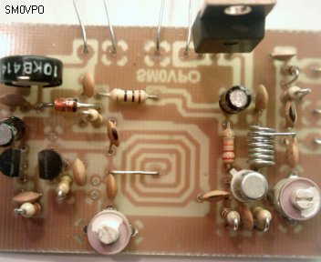
The completed V9 transmitter
The oscillator coil is etched on the PCB so the transmitter has no tendence to microphony. Long-term frequency stability in a room with regulated temperature was good. Total frequency drift in the first hour was under 25KHz, which is almost good enough for NBFM appalications. At 50MHz or 70MHz the stability will be quite satisfactory for NBFM.
The facility for both AM and FM mean that it is also suited for use as a TV transmitter. There is good seperation between AM and FM modulators so a 5.5MHz or 6MHz audio carrier can be injected into the FM input, whilst a simple complementary pair modulator will take care of video modulation. The transmitter will operate on both VHF band-I and band-II with very little modification.
Spectral purity is also very good. Every stage is linear and nothing is added that could cause harmonics or distortion to the output signal. I feel that this is an excellent project for the beginner to transmitters more complex than the "bug" variety, and it is useful for a variety of experimental purposes. It demonstrates that stability can be achieved, even with VHF LC oscillators.
A good view of the oscillator section
If you want to use it as a WBFM transmitter then you do not need to modify anything. The range is about double that of the V5, that is to say about 2km under "ideal" conditions. If used for NBFM in the lower ham bands then you should easily be able to get 10 - 20km with line-of-sight and decent gain antennas. If you use a decent comms receiver then this transmitter can be used for much greater distances. I would NOT recommend you trying it on the 2-metre band. The transmitter is not THAT stable!
So let us take another look at our original "hit list":
Battery voltage / frequency stability - Fixed
No immunity to supply voltage ripple - Fixed
Amplitude modulation also present - Fixed
No output level indication - Fixed
Buffer stage untuned and provides no gain - Fixed
TR1 biasing changes the oscillator conditions - Fixed
TR1 gives too great sensitivity for LINE levels - Fixed
Many constructors want a frequency control to twiddle - Fixed
Can be used for generating AM, FM and TV signals - New
Can even be used for sending DC and logic levels - New
Can be used for amateur radio bands (with care) - New
Simple to build, even though it uses coils - New
In addition to this I have introduced a coil for the constructor to wind. Before anybody asks, NO! I did not notice the relative humidity or the ambient temperature on the day I wound it. But seriously, PCB foil and component overlay drawings are available for download. Have fun with the project. Very best regards from Harry - SM0VPO
Appologies
Yes, when I built this prototype, I fed the regulator to the wrong side of the link, but I intended to add another link between the regulator and the PA. Of course, I forgot to do it for the final version, so if you want to use AM you will have to:
remove the link
cut the track from the 9v regulator
add a wire to connect the 9v to the oscillator
The link terminals then become the input from the modulation transformer, or one of them is the PA supply from the amplifier. But I am sure will see how it works out, it is quite easy.
Related Links
Downloads
40mW FM TRANSMITTER - Link
|
|
|
| |
Accurate LC Meter
Build your own Accurate LC Meter (Capacitance Inductance Meter) and start making your own coils and inductors. This LC Meter allows to measure incredibly small inductances making it perfect tool for making all types of RF coils and inductors. LC Meter can measure inductances starting from 10nH - 1000nH, 1uH - 1000uH, 1mH - 100mH and capacitances from 0.1pF up to 900nF. The circuit includes an auto ranging as well as reset switch and produces very accurate and stable readings. |
|
PIC Volt Ampere Meter
Volt Ampere Meter measures voltage of 0-70V or 0-500V with 100mV resolution and current consumption 0-10A or more with 10mA resolution. The meter is a perfect addition to any power supply, battery chargers and other electronic projects where voltage and current must be monitored. The meter uses PIC16F876A microcontroller with 16x2 backlighted LCD. |
|
|
|
60MHz Frequency Meter / Counter
Frequency Meter / Counter measures frequency from 10Hz to 60MHz with 10Hz resolution. It is a very useful bench test equipment for testing and finding out the frequency of various devices with unknown frequency such as oscillators, radio receivers, transmitters, function generators, crystals, etc. |
|
1Hz - 2MHz XR2206 Function Generator
1Hz - 2MHz XR2206 Function Generator produces high quality sine, square and triangle waveforms of high-stability and accuracy. The output waveforms can be both amplitude and frequency modulated. Output of 1Hz - 2MHz XR2206 Function Generator can be connected directly to 60MHz Counter for setting precise frequency output. |
|
|
|
BA1404 HI-FI Stereo FM Transmitter
Be "On Air" with your own radio station! BA1404 HI-FI Stereo FM Transmitter broadcasts high quality stereo signal in 88MHz - 108MHz FM band. It can be connected to any type of stereo audio source such as iPod, Computer, Laptop, CD Player, Walkman, Television, Satellite Receiver, Tape Deck or other stereo system to transmit stereo sound with excellent clarity throughout your home, office, yard or camp ground. |
|
USB IO Board
USB IO Board is a tiny spectacular little development board / parallel port replacement featuring PIC18F2455/PIC18F2550 microcontroller. USB IO Board is compatible with Windows / Mac OSX / Linux computers. When attached to Windows IO board will show up as RS232 COM port. You can control 16 individual microcontroller I/O pins by sending simple serial commands. USB IO Board is self-powered by USB port and can provide up to 500mA for electronic projects. USB IO Board is breadboard compatible. |
|
|
|
|
ESR Meter / Capacitance / Inductance / Transistor Tester Kit
ESR Meter kit is an amazing multimeter that measures ESR values, capacitance (100pF - 20,000uF), inductance, resistance (0.1 Ohm - 20 MOhm), tests many different types of transistors such as NPN, PNP, FETs, MOSFETs, Thyristors, SCRs, Triacs and many types of diodes. It also analyzes transistor's characteristics such as voltage and gain. It is an irreplaceable tool for troubleshooting and repairing electronic equipment by determining performance and health of electrolytic capacitors. Unlike other ESR Meters that only measure ESR value this one measures capacitor's ESR value as well as its capacitance all at the same time. |
|
Audiophile Headphone Amplifier Kit
Audiophile headphone amplifier kit includes high quality audio grade components such as Burr Brown OPA2134 opamp, ALPS volume control potentiometer, Ti TLE2426 rail splitter, Ultra-Low ESR 220uF/25V Panasonic FM filtering capacitors, High quality WIMA input and decoupling capacitors and Vishay Dale resistors. 8-DIP machined IC socket allows to swap OPA2134 with many other dual opamp chips such as OPA2132, OPA2227, OPA2228, dual OPA132, OPA627, etc. Headphone amplifier is small enough to fit in Altoids tin box, and thanks to low power consumption may be supplied from a single 9V battery. |
|
|
|
|
|
Arduino Prototype Kit
Arduino Prototype is a spectacular development board fully compatible with Arduino Pro. It's breadboard compatible so it can be plugged into a breadboard for quick prototyping, and it has VCC & GND power pins available on both sides of PCB. It's small, power efficient, yet customizable through onboard 2 x 7 perfboard that can be used for connecting various sensors and connectors. Arduino Prototype uses all standard through-hole components for easy construction, two of which are hidden underneath IC socket. Board features 28-PIN DIP IC socket, user replaceable ATmega328 microcontroller flashed with Arduino bootloader, 16MHz crystal resonator and a reset switch. It has 14 digital input/output pins (0-13) of which 6 can be used as PWM outputs and 6 analog inputs (A0-A5). Arduino sketches are uploaded through any USB-Serial adapter connected to 6-PIN ICSP female header. Board is supplied by 2-5V voltage and may be powered by a battery such as Lithium Ion cell, two AA cells, external power supply or USB power adapter. |
|
200m 4-Channel 433MHz Wireless RF Remote Control
Having the ability to control various appliances inside or outside of your house wirelessly is a huge convenience, and can make your life much easier and fun. RF remote control provides long range of up to 200m / 650ft and can find many uses for controlling different devices, and it works even through the walls. You can control lights, fans, AC system, computer, printer, amplifier, robots, garage door, security systems, motor-driven curtains, motorized window blinds, door locks, sprinklers, motorized projection screens and anything else you can think of. |
|
|
|