| |
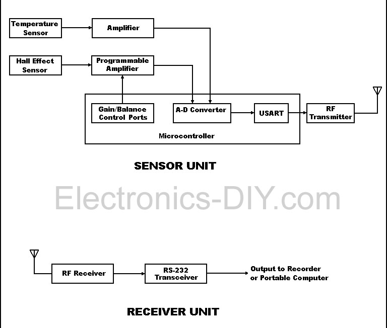
This device is designed to measure the torque in an automobile drive shaft and provide an output to a vehicle data recording system or a portable computer via an RS-232 interface. The received data can then be combined with RPM measurements from the data recording system to calculate horsepower. It consists of the sensor unit, (Figure 1), which attaches to the driveshaft, and the receiver unit, , which provides the serial output signal. The sensor unit is battery powered and communicates with the receiver via a 433 Mhz RF data link.The receiver unit is powered by the vehicle electrical system. Circuit operation is shown in the diagram.
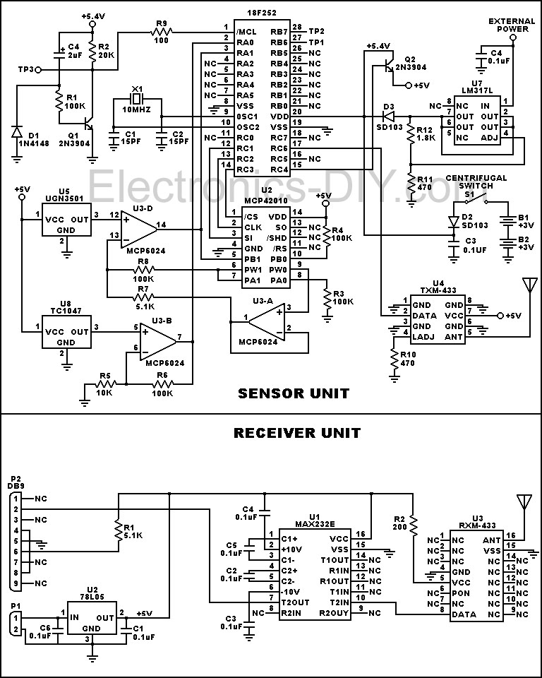
The sensor unit is contained in a cylindrical housing split along its axis to allow attachment without access to the driveshaft end. When the driveshaft experiences torsion it is transferred to the housing endplates. The inboard endplate contains a permanent magnet which is mounted against a Hall-effect sensor on the sensor plate. Since the sensor plate is attached to the outboard end plate it moves with it. The resulting angular deflection between the magnet and the sensor produces a signal which is proportional to the driveshaft torque.This signal is processed by the circuitry of the MCU PCB mounted axially between the endplates in the upper housing half. It is amplified by a section of an MCP6024 quad op-amp, the gain and operating point of which can be changed under program control via an MCP 42010 dual digital potentiometer. The amplifier output is converted to a digital output by the A-D converter of an 18F252 MCU. The digital value is then used as a vector into a lookup table in the MCU EEPROM data memory which is pre-loaded with values determined during calibration. Sensor variations with temperature are compensated for by reading the output of a TC1047 temperature sensor mounted on the sensor PCB in close proximity to the Hall-effect sensor. The temperature sensor output is also converted to a digital signal by the MCU and used to correct temperature induced errors. This circuitry operates from two lithium batteries mounted in the lower housing half to maintain assembly balance. To conserve power, these batteries are switched on by a centrifugal switch only when the shaft rotates. When testing or calibrating, external power is provided via connector sockets on the interface PCB mounted on the outboard end plate. This PCB also includes connector sockets for In-Circuit Serial Programming of calibration values.
Code:
; PROGRAMMABLE RESISTOR TEST PROCEDURE
; ----------------------------------------------------------------------------
; This procedure programs the MCP42100 Digital Potentiometer.
;-----------------------------------------------------------------------------
;
TEMP EQU 10H ; Temporary holding register.
COUNT EQU 11H ; Shift Count register.
;
ORG 0200H ;
;
BEGIN MOVLW B'11111111' ; Set RB0-RB7 as inputs.
MOVWF TRISB ;
MOVLW B'00000000' ; Set RC0-RC7 as outputs.
MOVWF TRISC ; D0 = /CS; D1 = Data; D2 = Clock
BCF INTCON2,7 ; Enable the internal pullups.
SER_OUT MOVLW 1 ;
MOVWF PORTC ;Set /CS = 1.
TESTBYT MOVLW 11H ;
MOVWF TEMP ; Set command byte to write pot 0.
MOVLW 8 ;
MOVWF COUNT ;
BCF PORTC,0 ; Set /CS = 0.
TESTBIT CLRWDT ;
RLCF TEMP ; Shift out the eight command bits.
BTFSC STATUS,CARRY ;
BSF PORTC,1 ; Set Data 1 or 0 as appropriate.
BTFSS STATUS,CARRY ;
BCF PORTC,1 ;
BSF PORTC,2 ; Toggle clock high, then low.
NOP ;
BCF PORTC,2 ;
DECFSZ COUNT ;
GOTO TESTBIT ; Continue for remaining bits.
MOVFF PORTB,TEMP ; Read the data input switch.
MOVLW 8 ;
MOVWF COUNT ;
TESTBT RLCF TEMP ; Shift out the eight data bits.
BTFSC STATUS,CARRY ;
BSF PORTC,1 ; Set Data 1 or 0 as appropriate.
BTFSS STATUS,CARRY ;
BCF PORTC,1 ;
BSF PORTC,2 ; Toggle clock high, then low.
NOP ;
BCF PORTC,2 ;
DECFSZ COUNT ;
GOTO TESTBT ; Continue for remaining bits.
BSF PORTC,0 ;
GOTO TESTBYT ; Return.
END
Related Links
Downloads
Horsepower Monitor - Link
|
|
|
| |
Accurate LC Meter
Build your own Accurate LC Meter (Capacitance Inductance Meter) and start making your own coils and inductors. This LC Meter allows to measure incredibly small inductances making it perfect tool for making all types of RF coils and inductors. LC Meter can measure inductances starting from 10nH - 1000nH, 1uH - 1000uH, 1mH - 100mH and capacitances from 0.1pF up to 900nF. The circuit includes an auto ranging as well as reset switch and produces very accurate and stable readings. |
|
PIC Volt Ampere Meter
Volt Ampere Meter measures voltage of 0-70V or 0-500V with 100mV resolution and current consumption 0-10A or more with 10mA resolution. The meter is a perfect addition to any power supply, battery chargers and other electronic projects where voltage and current must be monitored. The meter uses PIC16F876A microcontroller with 16x2 backlighted LCD. |
|
|
|
60MHz Frequency Meter / Counter
Frequency Meter / Counter measures frequency from 10Hz to 60MHz with 10Hz resolution. It is a very useful bench test equipment for testing and finding out the frequency of various devices with unknown frequency such as oscillators, radio receivers, transmitters, function generators, crystals, etc. |
|
1Hz - 2MHz XR2206 Function Generator
1Hz - 2MHz XR2206 Function Generator produces high quality sine, square and triangle waveforms of high-stability and accuracy. The output waveforms can be both amplitude and frequency modulated. Output of 1Hz - 2MHz XR2206 Function Generator can be connected directly to 60MHz Counter for setting precise frequency output. |
|
|
|
BA1404 HI-FI Stereo FM Transmitter
Be "On Air" with your own radio station! BA1404 HI-FI Stereo FM Transmitter broadcasts high quality stereo signal in 88MHz - 108MHz FM band. It can be connected to any type of stereo audio source such as iPod, Computer, Laptop, CD Player, Walkman, Television, Satellite Receiver, Tape Deck or other stereo system to transmit stereo sound with excellent clarity throughout your home, office, yard or camp ground. |
|
USB IO Board
USB IO Board is a tiny spectacular little development board / parallel port replacement featuring PIC18F2455/PIC18F2550 microcontroller. USB IO Board is compatible with Windows / Mac OSX / Linux computers. When attached to Windows IO board will show up as RS232 COM port. You can control 16 individual microcontroller I/O pins by sending simple serial commands. USB IO Board is self-powered by USB port and can provide up to 500mA for electronic projects. USB IO Board is breadboard compatible. |
|
|
|
|
ESR Meter / Capacitance / Inductance / Transistor Tester Kit
ESR Meter kit is an amazing multimeter that measures ESR values, capacitance (100pF - 20,000uF), inductance, resistance (0.1 Ohm - 20 MOhm), tests many different types of transistors such as NPN, PNP, FETs, MOSFETs, Thyristors, SCRs, Triacs and many types of diodes. It also analyzes transistor's characteristics such as voltage and gain. It is an irreplaceable tool for troubleshooting and repairing electronic equipment by determining performance and health of electrolytic capacitors. Unlike other ESR Meters that only measure ESR value this one measures capacitor's ESR value as well as its capacitance all at the same time. |
|
Audiophile Headphone Amplifier Kit
Audiophile headphone amplifier kit includes high quality audio grade components such as Burr Brown OPA2134 opamp, ALPS volume control potentiometer, Ti TLE2426 rail splitter, Ultra-Low ESR 220uF/25V Panasonic FM filtering capacitors, High quality WIMA input and decoupling capacitors and Vishay Dale resistors. 8-DIP machined IC socket allows to swap OPA2134 with many other dual opamp chips such as OPA2132, OPA2227, OPA2228, dual OPA132, OPA627, etc. Headphone amplifier is small enough to fit in Altoids tin box, and thanks to low power consumption may be supplied from a single 9V battery. |
|
|
|
|
|
Arduino Prototype Kit
Arduino Prototype is a spectacular development board fully compatible with Arduino Pro. It's breadboard compatible so it can be plugged into a breadboard for quick prototyping, and it has VCC & GND power pins available on both sides of PCB. It's small, power efficient, yet customizable through onboard 2 x 7 perfboard that can be used for connecting various sensors and connectors. Arduino Prototype uses all standard through-hole components for easy construction, two of which are hidden underneath IC socket. Board features 28-PIN DIP IC socket, user replaceable ATmega328 microcontroller flashed with Arduino bootloader, 16MHz crystal resonator and a reset switch. It has 14 digital input/output pins (0-13) of which 6 can be used as PWM outputs and 6 analog inputs (A0-A5). Arduino sketches are uploaded through any USB-Serial adapter connected to 6-PIN ICSP female header. Board is supplied by 2-5V voltage and may be powered by a battery such as Lithium Ion cell, two AA cells, external power supply or USB power adapter. |
|
200m 4-Channel 433MHz Wireless RF Remote Control
Having the ability to control various appliances inside or outside of your house wirelessly is a huge convenience, and can make your life much easier and fun. RF remote control provides long range of up to 200m / 650ft and can find many uses for controlling different devices, and it works even through the walls. You can control lights, fans, AC system, computer, printer, amplifier, robots, garage door, security systems, motor-driven curtains, motorized window blinds, door locks, sprinklers, motorized projection screens and anything else you can think of. |
|
|
|