| |
IR Remote Control Extender |
|
If you want control the DVD or TV/AV system that located in your living room via the remote control when you sleeping in your Bedroom. this IR extender will achieve this for you. Basically, it works as a repeater that moves the IR signal to a different location. This is an improved IR remote control extender circuit. It has high noise immunity, is resistant to ambient and reflected light and has an increased range from remote control to the extender circuit of about 7 meters. It should work with any domestic apparatus that use 36-38kHz for the IR carrier frequency.

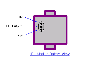
The main difference between this version and the previous circuit, is that this design uses a commercially available Infra Red module. This module, part number IR1 is available from Harrison Electronics in the UK. The IR module contains a built in photo diode, amplifier circuit and buffer and decoder. It is centerd on the common 38kHz carrier frequency that most IR controls use. The module removes most of the carrier allowing decoded pulses to pass to the appliance. Domestic TV's and VCR's use extra filtering is used to completely remove the carrier. The IR1 is packaged in a small aluminium case, the connections viewed from underneath are shown below:
How It works:
The IR1 module (IC3) operates on 5 Volt dc. This is provided by the 7805 voltage regulator, IC1. Under quiescent (no IR signal) conditions the voltage on the output pin is high, around 5 volts dc. This needs to be inverted and buffered to drive the IR photo emitter LED, LED2. The buffering is provided by one gate (pins 2 & 3) of a hex invertor the CMOS 4049, IC2. The IR1 module can directly drive TTL logic,but a pull-up resistor, R4 is required to interface to CMOS IC's. This resistor ensures that the signal from a remote control will alternate between 0 and 5 volts. As TTL logic levels are slightly different from CMOS, the 3.3k resistor R4 is wired to the +5 volt supply line ensuring that the logic high signal will be 5 volts and not the TTL levels 3.3 volts. The resistor does not affect performance of the IR module, but DOES ensure that the module will correctly drive the CMOS buffer without instability.
The output from the 4049 pin 2 directly drives transistor Q1, the 10k resistor R1 limiting base current. LED1 is a RED LED, it will flicker to indicate when a signal from a remote control is received. Note that in this circuit, the carrier is still present, but at a reduced level, as well as the decoded IR signal. The CMOS 4049 and BC109C transistor will amplify both carrier and signal driving LED2 at a peak current of about 120 mA when a signal is received. If you try to measure this with a digital meter, it will read much less, probably around 30mA as the meter will measure the average DC value, not the peak current. Any equipment designed to work between 36 and 40kHz should work, any controls with carrier frequencies outside this limit will have reduced range, but should work. The exception here is that some satellite receivers have IR controls that use a higher modulated carrier of around 115KHz. At present, these DO NOT work with my circuit, however I am working on a Mark 3 version to re-introduce the carrier.
Parts List:
C1 100u 10V
C2 100n polyester
R1 10k
R2 1k
R3 33R 1W
R4 3k3
Q1 BC109C
IC1 LM7805
IC2 CMOS 4049B
IC3 IR1 module
LED1 Red LED (or any visible colour)
LED2 TIL38 or part YH70M
Testing:
This circuit should not present too many problems. If it does not work, arm yourself with a multimeter and perform these checks. Check the power supply for 12 Volt dc. Check the regulator output for 5 volt dc. Check the input of the IR module and also Pin 1 of the 4049 IC for 5 volts dc. With no remote control the output at pin 2 should be zero volts. Using a remote control pin 2 will read 5 volts and the Red LED will flicker. Measuring current in series with the 12 volt supply should read about 11mA quiescent, and about 40/50mA with an IR signal. If you still have problems measure the voltage between base and emitter of Q1. With no signal this should be zero volts, and rise to 0.6-0.7 volts dc with anIR signal. Any other problems, please email me, but please do the above tests first.
PCB Template:
Once again a PCB template has been kindly drafted for this project by Domenico.
Alternatives to IC3:
The part number IR1 from Harrison Electronics is no longer available. They do supply an alternative IR decoder which I have tested and works. Other alternative Infrared decoders are shown below, note however that all DO NOT share the same pinout. I advise anyone making this to check the corresponding data sheets.
Vishay TSOP 1738
Vishay TSOP 1838
Radio Shack 276-0137
Sony SBX 1620-12
Sharp GP1U271R
Equipment Controlled Successfully:
If you have built this circuit and it works successfully please let me know and I will build the list. Email details of the Manufacturer, device and remote control model number. The remote model number is usually on the front or back of the remote.
Related Links
Downloads
IR Remote Control Extender - Link
|
|
|
| |
Accurate LC Meter
Build your own Accurate LC Meter (Capacitance Inductance Meter) and start making your own coils and inductors. This LC Meter allows to measure incredibly small inductances making it perfect tool for making all types of RF coils and inductors. LC Meter can measure inductances starting from 10nH - 1000nH, 1uH - 1000uH, 1mH - 100mH and capacitances from 0.1pF up to 900nF. The circuit includes an auto ranging as well as reset switch and produces very accurate and stable readings. |
|
PIC Volt Ampere Meter
Volt Ampere Meter measures voltage of 0-70V or 0-500V with 100mV resolution and current consumption 0-10A or more with 10mA resolution. The meter is a perfect addition to any power supply, battery chargers and other electronic projects where voltage and current must be monitored. The meter uses PIC16F876A microcontroller with 16x2 backlighted LCD. |
|
|
|
60MHz Frequency Meter / Counter
Frequency Meter / Counter measures frequency from 10Hz to 60MHz with 10Hz resolution. It is a very useful bench test equipment for testing and finding out the frequency of various devices with unknown frequency such as oscillators, radio receivers, transmitters, function generators, crystals, etc. |
|
1Hz - 2MHz XR2206 Function Generator
1Hz - 2MHz XR2206 Function Generator produces high quality sine, square and triangle waveforms of high-stability and accuracy. The output waveforms can be both amplitude and frequency modulated. Output of 1Hz - 2MHz XR2206 Function Generator can be connected directly to 60MHz Counter for setting precise frequency output. |
|
|
|
BA1404 HI-FI Stereo FM Transmitter
Be "On Air" with your own radio station! BA1404 HI-FI Stereo FM Transmitter broadcasts high quality stereo signal in 88MHz - 108MHz FM band. It can be connected to any type of stereo audio source such as iPod, Computer, Laptop, CD Player, Walkman, Television, Satellite Receiver, Tape Deck or other stereo system to transmit stereo sound with excellent clarity throughout your home, office, yard or camp ground. |
|
USB IO Board
USB IO Board is a tiny spectacular little development board / parallel port replacement featuring PIC18F2455/PIC18F2550 microcontroller. USB IO Board is compatible with Windows / Mac OSX / Linux computers. When attached to Windows IO board will show up as RS232 COM port. You can control 16 individual microcontroller I/O pins by sending simple serial commands. USB IO Board is self-powered by USB port and can provide up to 500mA for electronic projects. USB IO Board is breadboard compatible. |
|
|
|
|
ESR Meter / Capacitance / Inductance / Transistor Tester Kit
ESR Meter kit is an amazing multimeter that measures ESR values, capacitance (100pF - 20,000uF), inductance, resistance (0.1 Ohm - 20 MOhm), tests many different types of transistors such as NPN, PNP, FETs, MOSFETs, Thyristors, SCRs, Triacs and many types of diodes. It also analyzes transistor's characteristics such as voltage and gain. It is an irreplaceable tool for troubleshooting and repairing electronic equipment by determining performance and health of electrolytic capacitors. Unlike other ESR Meters that only measure ESR value this one measures capacitor's ESR value as well as its capacitance all at the same time. |
|
Audiophile Headphone Amplifier Kit
Audiophile headphone amplifier kit includes high quality audio grade components such as Burr Brown OPA2134 opamp, ALPS volume control potentiometer, Ti TLE2426 rail splitter, Ultra-Low ESR 220uF/25V Panasonic FM filtering capacitors, High quality WIMA input and decoupling capacitors and Vishay Dale resistors. 8-DIP machined IC socket allows to swap OPA2134 with many other dual opamp chips such as OPA2132, OPA2227, OPA2228, dual OPA132, OPA627, etc. Headphone amplifier is small enough to fit in Altoids tin box, and thanks to low power consumption may be supplied from a single 9V battery. |
|
|
|
|
|
Arduino Prototype Kit
Arduino Prototype is a spectacular development board fully compatible with Arduino Pro. It's breadboard compatible so it can be plugged into a breadboard for quick prototyping, and it has VCC & GND power pins available on both sides of PCB. It's small, power efficient, yet customizable through onboard 2 x 7 perfboard that can be used for connecting various sensors and connectors. Arduino Prototype uses all standard through-hole components for easy construction, two of which are hidden underneath IC socket. Board features 28-PIN DIP IC socket, user replaceable ATmega328 microcontroller flashed with Arduino bootloader, 16MHz crystal resonator and a reset switch. It has 14 digital input/output pins (0-13) of which 6 can be used as PWM outputs and 6 analog inputs (A0-A5). Arduino sketches are uploaded through any USB-Serial adapter connected to 6-PIN ICSP female header. Board is supplied by 2-5V voltage and may be powered by a battery such as Lithium Ion cell, two AA cells, external power supply or USB power adapter. |
|
200m 4-Channel 433MHz Wireless RF Remote Control
Having the ability to control various appliances inside or outside of your house wirelessly is a huge convenience, and can make your life much easier and fun. RF remote control provides long range of up to 200m / 650ft and can find many uses for controlling different devices, and it works even through the walls. You can control lights, fans, AC system, computer, printer, amplifier, robots, garage door, security systems, motor-driven curtains, motorized window blinds, door locks, sprinklers, motorized projection screens and anything else you can think of. |
|
|
|


