| |
Having decided to build an ultra-compact design, using a spare LM4780 seemed like an obvious plan. Having said that, I might choose a different IC if I didn't already have one to hand. The LM4780 contains two LM3886 dies (reference) giving 60 watts per channel, which is rather more than required this application. National Semiconductor make an enormous range of IC's with differing power levels and configurations, and there are plenty of possible candidates for this application - after all, we only need a few watts as this amplifier will principally be driving small speakers on the computer desk.
Basic design requirements:
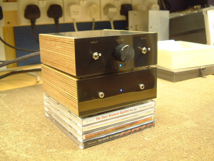
I wanted the amplifier to take its main visual "cues" from the Audax mini-monitors it will be powering. So the case will have the same width and depth, although in practice I don't plan to place the amplifier on top of a speaker.
I also took some design ideas from my Musical Fidelity A1. The top panel forms the heatsink - not the most efficient arrangement, but sufficient for this application. Also, as the actual amplifier could be much smaller than one of these speakers, I decided to recess the rear panel. This means that all the connectors are hidden by the sides and rear panel - a detail of the A1 that I've always liked.
As this is primarily to be used as a PC amplifier, one input would be sufficient. But I added a second input to make the amplifier more "general purpose", should I decide to use it elsewhere.
While the amplifier will probably be switched off by the daytime breaker in the workshop, I decided that a standby or mute mode would be useful as the "outboard" power supply was originally intended to be hidden away. The LM4780 has a "mute" function, and using this is much easier and preferable than any of the alternatives.
Finally, because of the compact dimensions, heat was likely to be a problem. This means that some form of thermal cutout is required. But note that this isn't to protect the IC - these have comprehensive inbuilt protection and are more than capable of looking after themselves. Rather, this is to protect people who might come into contact with the amplifier. As mentioned, the top panel forms the heatsink so the temperature of this should be kept to safe values!
Inverting or non-inverting?
When I first built a Gainclone back in 2003, the inverting configuration was all the rage, and pretty much every forum member wrote that this was hugely superior to the more conventional non-inverting layout. Since then, things seemed to have changed, and now everyone is saying that non-inverting is the way to go. Perhaps this says more about group-dynamics than amplifiers?
My LM3875 gainclones were inverting for the experiments that have been documented, but since writing up the results, I experimented briefly with non-inverting, and have to report that the differences really were marginal. To put it into context, upgrading the power supply to dual-mono operation was much more significant. Having said that, YMMV (your mileage may vary) because inverting mode presents a much lower impedance to the preamp - I wouldn't be surprised if some of the reported differences were due to this. Easily tested for by placing the input resistor from your inverting amplifier in parallel with the input to the non-inverting version.
So I chose the non-inverting configuration for this amplifier as this enables a more reasonable input impedance...
Power supply:
For reasons of space, the PSU will be a single unit supplying both channels. Also, having separate supplies for left and right channels is inconvenient - the point-to-point wiring will be hard enough as it is!
A star earth point will be implemented right next to the IC. The external PSU will generate a pair of supply potentials which are completely independent, and will only become a "split" supply when joined by this star earth.
After completing prototyping and construction of the amplifier, I performed some initial experiments to determine the best power supply configuration. I say "initial" because my reference hi-fi equipment is currently in storage due to the house move. However, using the workshop hi-fi components (Technics SLPG480 and Rogers dB101's) and my LS3/5a's, I determined the following:
220uF per rail decoupling capacitors mounted directly on the chip (Panasonic FC's)
6600uF per rail smoothing capacitors in the PSU, made up from 3300uF, 35V Panasonic FC's. I tried a range of values and a number of different types, but these gave the best results. Putting a pair of 3300uF's in parallel halves the ESR and ESL of the components, and these sounded better than a single pair of cheap, no-name 10,000uF devices I tried.
I played with "snubbers" at the power supply, but couldn't hear an appreciable difference with the test source and speakers. I wonder if the tightly twisted pairs in the special power supply umbilical lead was an issue here? I did find that adding 100nF per rail at the power supply was beneficial for reducing the effects of mains-bourne interference (although this amplifier seems very good in this regard - much better than the Arcam Alpha 2 currently in the workshop). One thing for the future (when the ATC's are available again) - experimenting with adding a snubber to the IC...
With this amplifier and the available source components and speakers, I couldn't hear a worthwhile difference between a standard bridge and discrete MUR860's.
The 120VA 18V transformer that I used for my original gainclone prototype sounded fine with this low-powered amplifier. I tried a 200VA unit and couldn't hear a significant difference with the available speakers.
Other than initially powering the amplifier from a bench power supply, I didn't experiment further with regulation. I felt that the above measures achieved a level of sound quality that was easily in excess of my expectations and requirements!
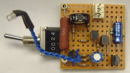
The power supply has an LED, powered by an extra winding that I added to the transformer - about 30 turns of fine enamal-coated wire. However, I didn't want the LED flickering at 50Hz, so I added a simple half-wave rectifier:
The analogue design:
This schematic shows the analogue signal path:
The input signals are applied to the source-select switch, a DPDT toggle switch with gold-plated contacts. From there, the signal is applied to volume potentiometer via an ultrasonic filter (R1 and C1) with a turnover frequency of around 2-300KHz with typical source impedances.
From the pot, the signal passes through C3 and R5 to the power amplifier IC. R5 ensures the amplifier remains stable during power up/down, and eliminating the risk of parasitic oscillations when the volume control is near or at minimum. In normal use, it plays no part in the signal path because the input draws no current at audio frequencies, therefore no voltage is dropped across it.
The feedback resistors were chosen to give a convenient value of gain (x25.54, or 28dB). It was simply a matter of choosing low values for avoid Johnson noise (combined impedances less than around 2K) while ensuring that they were components that I had in stock.
Finally, there is an output Zobel network. Generally, Gainclones are synonymous with simplicity, and this design philosophy normally results in the omission of these components. My initial prototypes managed without them, but I found that adding them improved the amplifiers immunity to RF. As always, YMMV.
The control circuit:
None of my projects are complete without a handful of transistors!
The complete circuit is neater than it appears. There are 3 distinct sections - a temperature sensing circuit, an LED flasher, and a power supply - as you'll see, these blocks are tightly integrated resulting in a low component count.
To avoid unbalancing the supplies and inducing DC currents into the earth scheme unnecessarily, the whole circuit is placed between the positive and negative supply rails. As the mute connections of the IC need to be brought down to the negative supply rail, the temperature sensor is placed down on this rail.
The sensor is a classic 2-transistor Schmitt trigger. TR2 switches the mute current directly - this is one of only two components in the whole design that "sees" the whole supply voltage of 50-60 volts, so it's a BC546.
For reasons that will be explained shortly, the sensing circuit runs off of 3.3 volts. RT1, an NTC thermistor, is connected in a potential divider that feeds the input to the Schmitt trigger. As the temperature rises, the potential on the base of TR1 rises. At some point, it can begin to conduct, and when this happens TR2 starts to turn off. As the collector current falls in this device, the potential across R17 also falls. However, the emitter of TR1 is connected to this point, so this means the VBE of TR1 is increased, causing it to conduct more. This is positive feedback, and will cause the output current to fall sharply and cleanly. The 33 ohm resistor introduces hysteresis, which means that the temperature must fall to something below the original "trip point" before normal operation can be resumed.
The mute switch is wired across the thermistor, and when activated, simply shorts out the device, simulating a gross over-temperature situation. Therefore, the audio is muted.
This circuit requires a tiny operating current - measured in micro-amps, rising to around 3mA when the mute switch is operated. The supply to this sensing circuit is simply regulated to 3.3 volts by the zener diode ZD1, with decoupling provided by C10. Current is supplied via R22, but notice that the power LED is placed in series. This is an economic way of powering both the sensing circuit and the LED. By powering this circuit between the rails, the resulting high value dropper resistor approximates current drive, ensuring that the LED brightness is relatively constant and not noticeably affected by the supply rails dropping under load.
The final section is the LED flasher. The two transistors form the classic two-terminal flasher circuit, and this circuit is normally placed in series with a load. However, I placed this circuit in parallel with the load. This means that when the transistors conduct, the LED is shorted out. When the LED is on, there is enough voltage dropped across it to power the flashing circuit (approx. 3.5 volts). Surprisingly, it works just as well when using a green or yellow LED (VF=2V approx.), and will also work with a red LED (VF=1.5V approx.) with a resistor value change.
Deciding to place the circuit in parallel was a good move. As all the components within the flasher circuit operate from the forward drop of the LED, they don't need to be rated to withstand the 50-60 volts available from the supply rails. So standard BC548/558 devices can be used, and the electrolytic timing capacitor can be a small, low voltage device. But all of this depends on the LED being present in the circuit, so for this reason, the LED must be soldered in place (i.e., not on a separate connector). Should the LED fail, it will probably go short-circuit which is perfectly safe, but if it goes open-circuit, there is a slight chance of problems. However, the 5K6 resistor limits the available current to around 10mA, which should prevent any nasty explosions.
Finally, note D1 that joins the flasher circuit to the sensor output. When the temperature is normal, and the mute switch is in the "unmute" position, the voltage at the collector of the BC556 will be close to 0V (with respect to the negative rail). Thus the diode conducts, preventing the TR4 in the flasher circuit from conducting. Therefore, the LED is on continuously. When muted, the voltage at the BC546 rises, the diode becomes reverse-biased and the LED starts to flash.
This explains why the supply to the temperature sensor is so very low (3.3V). When muted, the voltage at the base of TR4 is negative wrt to its emitter which is held to 3.3V. Transistors have a limit on the amount of reverse-bias that can be applied to the base-emitter junction - normally around 5 or 6 volts. The zener diode ensures that the reverse-bias is held to less than around 3 volts.
So a neat little circuit that has a low component count and should be reliable as only one component generates any heat, and this has been over-specified by a factor of 4.
Construction:
I used point-to-point wiring with this amplifier - challenging because the pin spacing of the LM4780 is so tight, but much quicker and easier than designing a PCB and getting it etched...
My approach to point-to-point wiring is different to most examples that I've seen, where connections rely on the solder for mechanical strength. This is not conducive to long-term reliability, especially in a power amplifier where high operating temperatures are encountered. To compound the problem, the tight three-dimensional layout that results from this construction technique makes future maintenance difficult.
I firmly believe that all connections should rely on the physical connection and not the solder. So all connections are firmly made by wrapping wires around each other. This is much more time-consuming than normal, and is also very fiddly, especially at the beginning. But, as you progress it becomes easier than "normal" p2p construction, where the heat from soldering new connections can damage solder joints made previously - in extreme cases, components literally fall off! It's very frustrating when this happens!
As mentioned, I wanted to compliment the design of my Audax mini-monitors by using birch ply for side panels, and also using identical dimensions. I quickly realised that the amplifier could be much smaller than the speakers, so I decided to use the extra depth to hide the connectors. The extra surface area of the aluminium top panel helps with heat sinking. Ignoring this "overhang", the amplifier only measures 12.5 by 7 by 4.5 centimetres - is this the smallest Chip-Amp out there?
Assembling the amplifier:
The LM4780 has 27 pins, spaced apart by just 1mm. Eight of these are not connected to anything and can be removed. Next, the pins were straightened, and pointed in one of 3 basic directions - horizontally for power, vertically for signal inputs and outputs, and at 45 degrees for ground and mute connections.
For the wiring, I decided to use enamel coated wire. This builds in a safety feature - should the internal wiring be disturbed, the chances of a short-circuit are very much reduced.
The enamel coating will burn away given enough heat from a soldering iron. However, I've not convinced that the resulting fumes are good for your health, and I'm also not happy about the amount of time this process takes. It's fine for assembling crossovers, but not when performing microsurgery with a tiny chip-amp. So, using a scalpel, I prepared the wires by scraping off the enamel and pre-tinning the exposed copper wire:
Prepared IC and wire (28K)
This next image shows the initial connection. The chip is held in a vice, and the prepared wire has been loosely attached to one of the pins with a tiny dab of solder. Note how all the pins have been colour-coded with permanent markers - just to help prevent any silly mistakes!
Look carefully at the middle two "black" pins, and you'll see that they have been carefully wrapped around the wire, ready for soldering.
First connections (35K)
Here, the two power leads have been successfully attached to the IC. They are separated by a good few millimetres, but the enamel insulation will prevent any nasty surprises.
Both power connections done (29K)
Next I turned my attention to the signal connections, adding the 27K feedback resistors you can see below. These resistors are 1/8 watt - roughly 3mm long. The output and inverting-input pins have been folded back, and the resistors sit on top of the package. Note also how some green sleaving has been applied to the ground pins:
Feedback resistors (32K)
Next additions were the ground wire (same technique as the power connections), and the 1K1 resistors that connect between ground and the inverting inputs. These resistors are bigger 1/4 versions as these were available in my parts bin.
Ground and mute connections (27K)
With the ground wire in place, I could think about the components needed on the non-inverting inputs. Before installing these, I connected both the "mute" pins together with some thinner enamal-coated wire, cutting these nice and short so that they wouldn't touch the next resistors. This picture shows the 1/8 watt 1K and 22K resistors. I also added some green sleeving to the non-inverting inputs for peace of mind. Note how the various resistor leads form the input and output connections...
All resistors mounted (28K)
Finally, this view from below shows the power rails and earth more clearly. I was pretty pleased with how this turned out, and at this point was able to quickly test the assembly to prove that I'd not made any silly mistakes. Obviously, it was a bit early for any sound quality judgements!
Building the case:
This was built entirely from recycled or leftover materials. The sides were formed from the leftovers from hollowing out the layers of the mini-monitors, and the metal was rescued from skips! The smaller pieces of angle-stock are 25mm by 40mm, and the larger piece is 50mm by 100mm (roughly!).
Raw materials (26K)
The first step was to make the sides - here are two layers of 23mm birch after being glued together. Much planing and sanding is required at this point...
Side panels underway (56K)
I decided to use my 9.5mm rebating bit in the router to cut the recesses for the chassis and top and bottom panels - this would be easier than making jigs to guide the router. However, this relied on the insides of panels being perfectly straight. This is a good thing, because I like the insides of my projects to be just as perfect as the outside ;-)
Finished side panels (52K)
Here is the chassis, after most of the drilling had been completed. As you can see, the various sockets have been mounted, and the IC has been attached. Note how the sil-pad was left large enough to cover the point-to-point connections - just in case:
Chassis, with IC (41K)
Final wiring of the audio section:
At this point, things get very hard to reverse. So I had to be sure the chassis was mechanically finished before proceeding with the final stage of wiring.
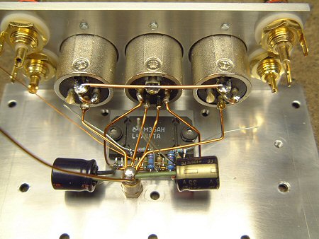
This picture shows the star-earth, and the connections to the XLR sockets. Also, we've added the 220uF decoupling capacitors (Panasonic FC's - long-life, high temperature devices). The lead-outs on these could have been shorter but the capacitors would have interfered with the volume potentiometer - if I ever change the pot in the future, I could shorten the lead-outs.
I chose to use XLR sockets for a number of reasons. Most obviously, they are rugged, and of very high quality. But, I was worried about using standard 4mm binding posts when they were so close to the input connectors. This is a non-inverting amplifier, and any stray capacitance between input and output connectors will form a route for positive feedback, with the very real risk of the amplifier turning into an oscillator! The grounded bodies of the XLR sockets offer good screening, reducing the risks. This point is sometime overlooked by people building compact amplifiers!
Chassis wiring (52K)
The next stage was to install the input wiring. The cables are high quality video leads, rescued from an old VCR. I made use of the existing termination for neatness. Note the P-clamp that helps to keep the wiring tidy. The black wire is the "pigtail" connected to the screens that connects to the signal earth.
Also, the output wiring as been added, including Zobel components installed on the output sockets. In an ideal world, these would be connected directly to the IC and the star earth, and if this amplifier was any less compact, I would perhaps worry about this.
Input wiring (52K)
Moving forward, the potentiometer components were assembled. The input capacitors and ultrasonic filters can be seen here. The grey 2u2 capacitors are held with double-sided sticky pads, and as you'll see later, their position is for a reason... Note also the signal ground, the bottom-right pin...
Potentiometer and front sub-panel (47K)
Then the sub-panel is secured to the chassis... The signal from the input switch travels via the 1K resistors into the potentiometer. Note the soldered connections on the right side of the capacitors - these are made using the substandard method that I tried to avoid everywhere else - indeed contrast them with the secure connections on the left side of the capacitor. This was for a reason, however. I reckoned that I might need to separate the pot from the chip assembly at some point in the future, so I made these connections easy to desolder. I'm not too worried about reliability here, as it's the easiest to reach when necessary.
Front panel installed (48K)
The final detail was to add the connection between chassis and the star earth, as shown here:
Star earthing (30K)
Installing the thermal sensor/mute/LED board:
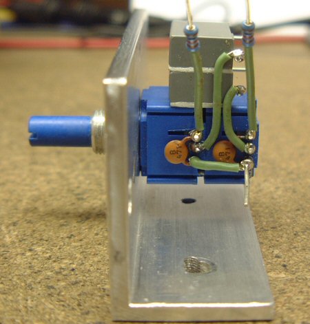
As the thermal sensor doesn't have to be in close contact with the IC, I decided to minimise internal wiring by placing it directly on the control board. The power LED also connects directly to this board - this is a standard 3mm device that has been filed down to make it fit better into the 3mm front sub-panel.
The 2W power resistor is rather over-specified - the actual power dissipation is around 0.5 watts. But I had one of these spare, and using a large resistor will help reliability by keeping the operating temperature down.
Control circuit (28K)
This small assembly is supported entirely by the toggle switch, as shown here. There is a depression drilled into the chassis for the thermistor to sit in, and a plastic insulating sleeve fitted to the M3 pillar. There is a pair of these pillars which the bottom panel attaches to.
Note also how the grey input capacitors hold the LED in place:
Control circuit installed (41K)
Front Panel:
This project gave me the opportunity to try out an idea that I had years ago - using an overhead transparency film to achieve a professional front panel.
This picture shows the transparency. Looking closely, you might notice a black square around the LED - this is because the opening is 2mm - smaller than the actual LED. One layer has insufficient contrast, so a second layer is stuck behind using a scrap of white tape from my labelling machine which also acts as a defuser to ensure a nice, even light.
Front panel (21K)
And here it is, installed on the chassis along with the perspex which is simply held on by the switches and potentiometer fixings. You can see through the transparency because the toner coverage isn't terribly thick, but this isn't an issue when the case is fully assembled as there is no light source behind the panel.
Front panel assembled (32K)
The visibility of the text is only just acceptable - the perspex is tinted, but not heavily. The aluminium was polished to make it as reflective as possible, but I applied some white tape to improve the contrast ratio. Another option would be to backlight the legends, but this won't work here without seriously modifying the chassis and front sub-panel.
Power Supply:
Initially, I assumed that the outboard power supply would be a simple affair - built into a standard diecast aluminium enclosure, for example. As it was intended to be hidden out of site, there were no physical limitations placed on the electrical design.
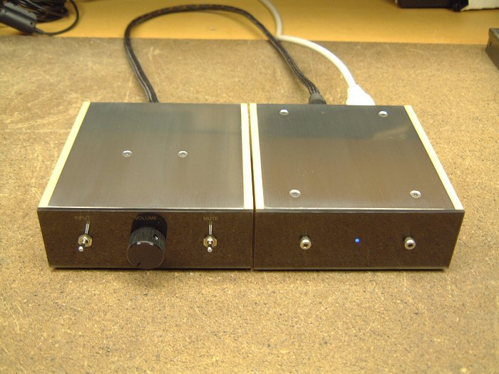
But once the design had been finalised, I began to realise just how compact it could be. It soon became apparent that I could fit everything into a box that matched the amplifier...
So the final solution uses birch ply side panels, two pieces of angle stock to form the chassis, and 1mm aluminium to form the top and bottom panels - these panels clamp the torroidal transformer in place.
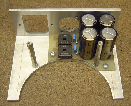
The first step was to prepare the chassis. Two pieces of angle-stock were cut down and the round opening was cut to allow for the transformer. Fitting in a 120VA transformer into a 45mm high box was going to be tight - there was no question of recessing the rear panel to hide the connectors this time!
Next the wooden sides were made. These were slightly easier because the 9.5mm rebate didn't have to stop part-way along the piece. You can see that the rebate continues along the rear panel.. Also, an area had to be removed to make way for the smoothing capacitors.
Next I made a PCB for the supply. Like with the gainclone prototypes, this was made using a scalpel and excess copper was removed using heat from the soldering iron. You can't see it here, but I also made an insulator to sit between the PCB and the chassis. I used a very thin piece FR4, necessary because space here is tight.
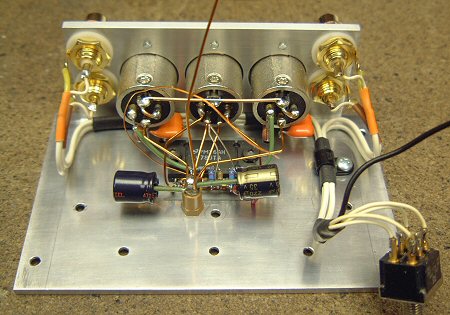
This view shows the underside of the PCB - as you can see the layout is very simple. To conserve the height, the component leads were laid flat before soldering - this also ensures a better contact, but makes future servicing a bit harder. To act as a spacer, I used some plastic bushes - the sort normally used for insulating semiconductors from heatsinks.
And here's the completed PCB in situ. Note how the DC output XLR connector just clears the bridge rectifiers - this was a neat solution. You can also see the spacers that the bottom panel are attached to...
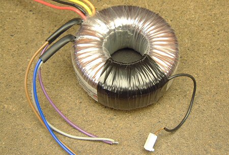
Next, I added a winding to the transformer to power the LED. This winding gives around 5 volts, from memory this needed around 30 turns. Because of the limited space, I used very thin enamel wire that didn't significantly alter the height. The windings were secured with insulating tape - the end of the tape runs were at the top of the transformer, so the transformer clamping will keep the tape secure...
This is the LED rectifier. I didn't want the LED flickering so I added the capacitor.
And this is how it fits onto the other half of the chassis. As with the amplifier, the 3mm LED has been filed down and locates into the hole. The LED holds itself in place, but is additionally retained by the transformer.
Next was the final assembly. The wires from the XLR connector and the secondary windings from the transformer are attached to the PCB, and the primary windings are wired up. Note the green earth wires that securely connect the two halves of the chassis to the mains earth connector in the IEC socket - also the shell of the XLR socket is earthed.
I also added an insulator to the top of the capacitors. As they age, they might expand and touch the bottom panel, causing a short circuit. You can see the perspex front panel, which like the amplifier, has a laser-printed transparency to define the power LED (there's currently no text, but that might change). As there are no controls (not even room for a power switch), the front panel is held on with a pair nice stainless steel hex bolts.
And here is the final assembly, with both wooden side panels attached. These hold the two halves of the chassis together - the thin top panel helps, but it primarily holds the transformer in place... As you can see, it's a squeeze - the PCB only just fits. You can see the four spacers that the bottom panel attach to - these have been covered with neoprene "Hellerman" sleeves to protect the transformer should it move and come into contact with them.
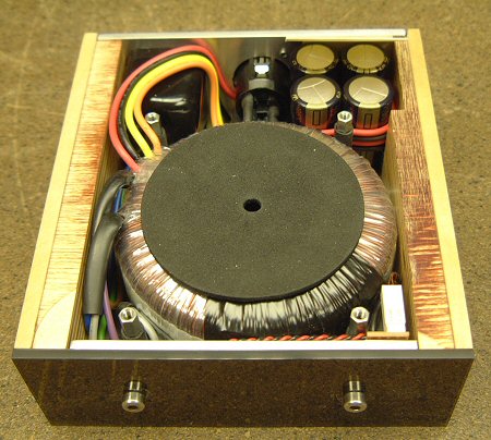
And finally, here's the top view, before the top panel is added. This panel is secured by four allen-bolts, and hides all the other fixings, including the low-tech wood-screws. This demonstrates that we really couldn't afford the 3mm thickness of the chassis...
The final construction worked well - as the insides are dominated by that 120VA torroid, and the resulting unit is very heavy for its size.
Conclusion:
Due to the house move, this project was built without the full resources of the workshop and the hi-fi, but despite this, I was pleased with the design and construction. I'll only be able to make a full assessment of the absolute sound quality and perhaps improve things once I've got my reference ATC's out of storage...
As a finished product, this amplifier is seriously cute, and has elicited lots of positive reaction from friends and colleagues. The design details, including the hiding of the connectors and the use of birch ply make for an interesting look.
The LM4780 runs slightly warmer than the LM3875 because it has a higher bias in the output stage. Some people report that the LM4780 runs very hot, but the problem isn't as bad as you might think. If you have a hot-running parallel design, study the datasheet and ask yourself if you really can omit everything - minimalism is good, but within limits!
The quiescent current is around 50mA per channel - compared to around 17mA for the LM3875. With 30V supply rails, this translates to 6 watts of heat with no signal - the case runs at around 12-15 degrees C above ambient under no-signal conditions. I quite like this heat - it reminds me of my old Musical Fidelity A1... Fortunately, because music has a high PMR (peak to mean ratio), moderate use doesn't raise the temperature much - the large amount of aluminum present in the chassis helps here as it causes a decent amount of thermal inertia. The overhanging top panel also helps, despite only being 1mm thick - what matters for heatsinking is surface area, and although it isn't optimally aligned for good convection, you can feel a healthy current of warm air rising from under the rear of the panel. The thermal sensor will mute the amplifier well before the chip has reached unsafe limits, ensuring reliable long-term operation.
Related Links
Downloads
LM4780 Power Amplifier - Link
|
|
|
| |
Accurate LC Meter
Build your own Accurate LC Meter (Capacitance Inductance Meter) and start making your own coils and inductors. This LC Meter allows to measure incredibly small inductances making it perfect tool for making all types of RF coils and inductors. LC Meter can measure inductances starting from 10nH - 1000nH, 1uH - 1000uH, 1mH - 100mH and capacitances from 0.1pF up to 900nF. The circuit includes an auto ranging as well as reset switch and produces very accurate and stable readings. |
|
PIC Volt Ampere Meter
Volt Ampere Meter measures voltage of 0-70V or 0-500V with 100mV resolution and current consumption 0-10A or more with 10mA resolution. The meter is a perfect addition to any power supply, battery chargers and other electronic projects where voltage and current must be monitored. The meter uses PIC16F876A microcontroller with 16x2 backlighted LCD. |
|
|
|
60MHz Frequency Meter / Counter
Frequency Meter / Counter measures frequency from 10Hz to 60MHz with 10Hz resolution. It is a very useful bench test equipment for testing and finding out the frequency of various devices with unknown frequency such as oscillators, radio receivers, transmitters, function generators, crystals, etc. |
|
1Hz - 2MHz XR2206 Function Generator
1Hz - 2MHz XR2206 Function Generator produces high quality sine, square and triangle waveforms of high-stability and accuracy. The output waveforms can be both amplitude and frequency modulated. Output of 1Hz - 2MHz XR2206 Function Generator can be connected directly to 60MHz Counter for setting precise frequency output. |
|
|
|
BA1404 HI-FI Stereo FM Transmitter
Be "On Air" with your own radio station! BA1404 HI-FI Stereo FM Transmitter broadcasts high quality stereo signal in 88MHz - 108MHz FM band. It can be connected to any type of stereo audio source such as iPod, Computer, Laptop, CD Player, Walkman, Television, Satellite Receiver, Tape Deck or other stereo system to transmit stereo sound with excellent clarity throughout your home, office, yard or camp ground. |
|
USB IO Board
USB IO Board is a tiny spectacular little development board / parallel port replacement featuring PIC18F2455/PIC18F2550 microcontroller. USB IO Board is compatible with Windows / Mac OSX / Linux computers. When attached to Windows IO board will show up as RS232 COM port. You can control 16 individual microcontroller I/O pins by sending simple serial commands. USB IO Board is self-powered by USB port and can provide up to 500mA for electronic projects. USB IO Board is breadboard compatible. |
|
|
|
|
ESR Meter / Capacitance / Inductance / Transistor Tester Kit
ESR Meter kit is an amazing multimeter that measures ESR values, capacitance (100pF - 20,000uF), inductance, resistance (0.1 Ohm - 20 MOhm), tests many different types of transistors such as NPN, PNP, FETs, MOSFETs, Thyristors, SCRs, Triacs and many types of diodes. It also analyzes transistor's characteristics such as voltage and gain. It is an irreplaceable tool for troubleshooting and repairing electronic equipment by determining performance and health of electrolytic capacitors. Unlike other ESR Meters that only measure ESR value this one measures capacitor's ESR value as well as its capacitance all at the same time. |
|
Audiophile Headphone Amplifier Kit
Audiophile headphone amplifier kit includes high quality audio grade components such as Burr Brown OPA2134 opamp, ALPS volume control potentiometer, Ti TLE2426 rail splitter, Ultra-Low ESR 220uF/25V Panasonic FM filtering capacitors, High quality WIMA input and decoupling capacitors and Vishay Dale resistors. 8-DIP machined IC socket allows to swap OPA2134 with many other dual opamp chips such as OPA2132, OPA2227, OPA2228, dual OPA132, OPA627, etc. Headphone amplifier is small enough to fit in Altoids tin box, and thanks to low power consumption may be supplied from a single 9V battery. |
|
|
|
|
|
Arduino Prototype Kit
Arduino Prototype is a spectacular development board fully compatible with Arduino Pro. It's breadboard compatible so it can be plugged into a breadboard for quick prototyping, and it has VCC & GND power pins available on both sides of PCB. It's small, power efficient, yet customizable through onboard 2 x 7 perfboard that can be used for connecting various sensors and connectors. Arduino Prototype uses all standard through-hole components for easy construction, two of which are hidden underneath IC socket. Board features 28-PIN DIP IC socket, user replaceable ATmega328 microcontroller flashed with Arduino bootloader, 16MHz crystal resonator and a reset switch. It has 14 digital input/output pins (0-13) of which 6 can be used as PWM outputs and 6 analog inputs (A0-A5). Arduino sketches are uploaded through any USB-Serial adapter connected to 6-PIN ICSP female header. Board is supplied by 2-5V voltage and may be powered by a battery such as Lithium Ion cell, two AA cells, external power supply or USB power adapter. |
|
200m 4-Channel 433MHz Wireless RF Remote Control
Having the ability to control various appliances inside or outside of your house wirelessly is a huge convenience, and can make your life much easier and fun. RF remote control provides long range of up to 200m / 650ft and can find many uses for controlling different devices, and it works even through the walls. You can control lights, fans, AC system, computer, printer, amplifier, robots, garage door, security systems, motor-driven curtains, motorized window blinds, door locks, sprinklers, motorized projection screens and anything else you can think of. |
|
|
|