| |
Building Noise Canceling Headphones |
|
In today’s hectic and noisy world, we are all searching for a little peace and quiet. Well, you might not be able to slip off to a tranquil forest for an hour or two, but you can block out background noise with the Noise-Canceling Headphones. The theory behind this project is that by picking up ambient sound with a microphone and reproducing it out of phase, we can actively cancel or "null" out background noise. In fact, several commercially available devices perform the same function. However, by building your own headset, you can add features not otherwise available and have fun while doing it!
Along with noise-features, the Active Noise-Canceling Headphones let you mix in an auxiliary line-level signal from a CD or tape player. That allows you to minimize background noise while quietly listening to music. The project also has a phase switch that will let you keep the microphone signals in phase, thus amplifying background sound. In addition, the design of the Noise-Canceling Headphones lends itself to several other interesting functions, which we will look at later.
How It Works. The electronics consist of three op-amp circuits; each built around one half of an NE5532 dual op-amp. Each circuit uses that op-amp in a different configuration. The first circuit is a non-inverting pre-amp, the second is a unity-gain phase-inverter, and the third is an inverting headphone amplifier. Since the Noise-Canceling Headphones is a stereo device, the circuit is actualty two identical circuits side-by-side. Only one channel will be described; the second channel works in exactly the same way.
Fig. 1. The Noise-Canceling Headphones is a simple phase-inverting amplifier. All inverted sounds played back through the headphones cancel out the original sounds, leaving nothing but silence. The amount of canceling can be adjusted for different situations. A CD player or cassette tape can be listened to if you want to "fill the quiet."
The schematic diagram in Fig. 1 shows the design of the electronics portion of the project. A headset-mounted microphone is connected to J1, a 1/8-inch stereo jack. Electret-condenser microphones need a 2- to 10-volt bias voltage for their internal FET pre-amps. That is supplied by R2. A voltage-dividing network, which also decouples the bias volt-age from the power supply, is provided by Rl and Cl. That is necessary due to the high gain of the entire signal chain.
The signals from the microphone then go to ICl-a. an NE5532 set up as a standard non-inverting pre-amp. The gain is set to one plus the ratio of R8/R6 in the feedback path. The total gain for that stage is about 31 dB. Resistor R4 provides a ground reference for the pre-amp. A pair of high-pass filters is formed by C2/R4 and C4/R6. Those filters block any DC that tries to slip through the pre-amp.
From the output of the pre-amp, the microphone signal is sent down two different paths. It feeds both one pole of Sl-a and the phase-inverter. The phase inverter is nothing more than a second NE5532 configured as a unity-gain inverting op-amp (IC2-a). The output of IC2-a is connected to the other pole of Sl-a. That way, Sl-a can select either the inverted or the non-inverted signal. The selected signal on Sl-a’s common pole goes to potentiometer R14-a. That potentiometer sets the level of the microphone signal feeding the headphone amplifier.
The headphone amplifier is built around IC3-a, a third NE5532 wired as an inverting op-amp stage. The gain here is set by the ratio of R19/R15. That type of op-amp configuration can be easily modified to add a summing feature by the inclusion of R17. The second input comes from an auxiliary line-level input that is attenuated by potentiometer R23-a.
There is a reason why 10K-ohms was chosen for the value of R15 and R17. Besides keeping the values of R19 manageable, the 10K-ohms resistors interact with the 100K-ohm linear potentiometers. The potentiometers then behave in a logarithmic fashion.
This is how that feature works: One end of the potentiometer is tied to ground because we are using it as a voltage divider. Because the sum-ming junction of an op-amp is at a virtual ground, the 10K ohm resistor is also essentially tied to ground. That affects the response of the potentiometer, As the potentiometer is rotated, there is a more pronounced increase in the output as the end of the potentiometer’s travel is reached. That causes a smooth increase in perceived loudness of the signal. Potentiometers with an audio taper are, of course, available, but a linear-taper unit is easier to obtain and costs less.
The output of the headphone amplifiers is coupled to output jack J3 through R21. That resistor provides overload protection to IC3-a in case the output is shorted. If you have never used an op-amp for driving headphones before, you are in for a nice surprise. The NE5532 will supply a 10-volt rms signal into a 600-ohm load with very little distortion. That works out to 166 mW of power. Most personal stereos only supply 20 to 30 mW of power to headphones.
A final note on using operational amplifiers as headphone amps: Most generic ones will not supply enough current to function properly. Some substitutes for the NE5532 that are known to work include the 0P275 from Analog Devices, the OPA2604 from Burr Brown, and the LM833 from National Semiconductor. Those components are available from several sources, including Digi-Key, Allied Electronics, and Jameco.
Construction. There are two parts to this project: building the electronics and modifying a pair of headphones. The circuit is relatively simple and can easily be assembled on a perfboard. One style of perfboard that simplifies construction is one having a pre-etched copper pattern on its solder side that connects groups of holes together. One example of that type of perfboard is Radio Shack #276-150.
The etched pattern on that board has a pair of buses that run the length of the board. Those buses are very convenient for power distribution. If you use that type of board for the Noise-Canceling Headphones, it is best to start by spacing out the three ICs on the board so that they straddle the buses. Then attach the power supply leads from each chip to the buses. It is then a simple matter of point-to-point wiring the rest of the circuit.
Check your work often while building the circuit. A common mistake many hobbyists make is not checking their work thoroughly enough. Often a few components are accidentally wired in backwards. The usual result is that the circuit will probably not work, the ICs could be damaged, and the electrolytic capacitors might explode!
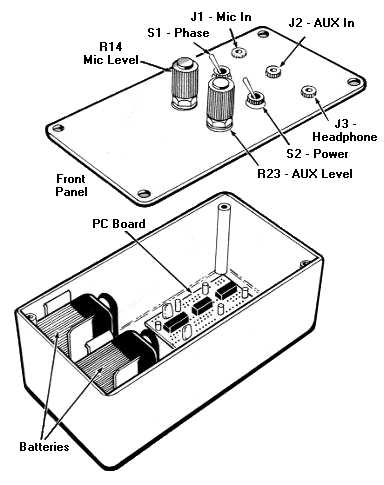
Fig. 2. The circuit board and batteries fit neatly into a simple project box. Keeping the wiring neat and following the layout shown here makes assembling the unit and changing the batteries easier.
When wiring the jacks, it is a good idea to follow the audio industry standards as to which jack connection is for which stereo channel. Normal standards for stereo connections are to connect the right channel to the ring and the left channel to the tip. The board and batteries are mounted in a suitable enclosure. A suggested layout for the components and control panel is shown in Fig. 2.
When selecting a case for the project, be sure that it is large enough to hold the circuit board and the two 9-volt batteries comfortably. After the front panel is laid out and drilled, check to make sure all the controls and jacks will fit. One method for labeling the front panel is to spray the entire panel with a flat color such as white or yellow. After applying transfer let-ters, seal the panel. Use several thin coats of a clear coating such as Crystal Clear by Krylon. The results are worth the effort. While the front panel is drying, we can start on the headphones.
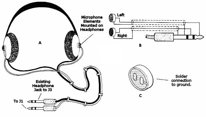
Fig. 3. The microphones are mounted on the earpieces of the headphones with a dab of silicone sealant. Tie both wires together in order to make the headphones more comfortable to wear (A). Follow the diagram in (B) when wiring the microphones. The left mic is connected to the plug’s tip and the right is connected to the ring. The ground connection on an electret microphone cartridge is easily identified by the solder connection between the terminal and the mic’s case (C).
Headphones with Ears. The headphones are a standard pair of aftermarket Walkman-type units. They sell for about $20 at most record or electronics stores. The headphones are modified by mounting two small electret-condenser microphones on the head-phones, one on each earpiece. That modification is shown in Fig. 3.
The key to making the headphones wearable is to use thin wires running to the microphones. An excellent source of thin audio cable is to buy another set of cheap headphones - the cheapest you can find. Cutting the wire off them will yield a shielded stereo cable that is thin and flexible. As an added bonus, the wire will have a l/8-inch stereo plug molded on to it already!
The best way to strip that type of wire is to roll a razor blade very carefully over the insulation without cutting the wire underneath. Once the insulation is cut, carefully pull it away from the wire. That method works especially well on Teflon-insulated wire. After you have prepped the wire, mark the wire that is connected to the ring and the one that goes to the tip of the jack. An ohmmeter makes that task easy.
Carefully solder the wires to the microphone elements. The easiest way to do that is to pre-tin the wires and melt the little dab of solder on the microphone element with the tinned wire beneath the soldering iron tip. Look carefully at the microphone. As shown in Fig. 3C, the terminal that is connected to the case of the microphone is the ground connection. The other terminal is the actual microphone output. Holding the microphone element in an alligator-clip holder will make the job much easier. After soldering on the microphone elements, it is good idea to test them prior to gluing them to the headphones. The wiring should follow Fig. 3B.
Mount the microphones on the headphones as shown in Fig. 3A. One way to attach the microphones to the headphones is to use a dab of silicone sealant. Using a toothpick or other suitable substitute, mold the silicone around the edges of the microphone element to smooth everything off. Be careful not to get any on the black felt surface - that is where the sound enters. Obviously, the left and right microphones should be attached to the left and right sides of the headphones, respectively. Trying to cancel out a sound on the right with a sound from the left will not work.
After the glue is dry, gather and bundle the wires together with several nylon tie wraps along the length of the wires. With the headphones complete, it is time to experiment with the Noise-Canceling Headphones.
Creating A Quiet Zone. For testing purposes, you should be in a quiet room with just a little background sound, such as a heater or air-conditioner fan. Plug in the microphone jack and the headphone jack, and put on the headphones. Turn both controls all the way down and turn the power switch on. Slowly turn up the microphone level. You should either hear the background sound increase or start to fade. If it increases, change the position of the phase switch. At some point, you should reach a "null" point where the background sound is at a minimum. If you adjust beyond the null, background sound will become louder as the out-of-phase signal exceeds the ambient sound level. Try talking aloud. If it sounds like you have a massive head cold and can barely hear yourself, the circuit is functioning properly.
Note that it is impossible to eliminate all incoming sound. Many things affect the ability to cancel out noise. The loudness of the incoming sound, the specific frequencies involved, and the position of the sound source all play a part in how well the headphones do their job. Feel free to experiment.
If everything is working fine, try connecting a CD player to J2. You will need a 1/8-inch -to- 1/8-inch patch cord similar to the ones used to connect portable CD players into a car stereo. After connecting the CD player, slowly turn up R23. It should sound clear with no distortion. Experiment with combining low levels on the CD player and canceling out room noise. The Noise-Canceling Headphones is the perfect device for environments that have a loud ambient sound level, such as rooms with loud ventilation systems.
Beyond Peace and Quiet. This project lends itself to many other uses. Several interesting applications will suggest themselves that do not require any additional hardware. For example, by switching the microphones to "in-phase," the unit can be used to assist hearing or improve hearing. Areas that can benefit include outdoor activities such as hunting or just observing nature.
Another unusual application for the Noise-Canceling Headphones is in binaural recording. Since we already have two microphones mounted in essentially the same place human ears are, all we have to do is send the headphone output to a tape recorder input. Binaural recordings put the listener directly in the sound field. The two microphones capture the exact phase and timing relationships of sound as we hear it. Those are the clues our ears use to determine the location of a sound.
Try this little experiment: record a person talking to you while you are wearing the headphones and have them walk around you in a circle. Then listen to the recording on the headphones. You will hear the person walk around you! The microphone elements used in this project feature full 20-Hz to 20-kHz frequency response. They provide a signal with surprisingly high fidelity.
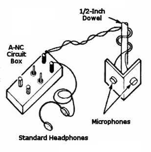
Fig. 4. Mounting both microphones angled apart at the end of a long stick makes an audio probe. It is very useful when you need to listen at a location that you can’ t reach.
Other interesting tools can be created by building different types of housings for the microphones. If two microphones are mounted on the end of a length of 1/2-inch dowel, an audio probe is the result (Fig. 4). It is wired similarly to Fig. 3B. That device lets you listen to things up close that you wouldn’t normally hear. It can be used to "sniff" out problems in mechanical equipment or to record things like hamsters chewing on cardboard. With the microphones mounted at an angle between 90 degrees and 120 degrees, you will have a stereo image of the sound source too!
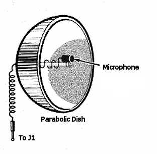
Fig. 5. A parabolic dish or lamp reflector makes a usable "Big Ear" microphone. The microphone is mounted at the focal point facing in towards the dish. Either one or two microphones can be mounted in the dish. If you build two, you can pick up stereo sounds.
An extension of the shotgun-style microphone is a "Big Ear." The general arrangement is shown in Fig. 5. The main component is a small parabolic dish. Place one or both microphones at the focal point of the dish and experiment away. Sources for parabolic dishes can be as close as a local hardware store. A simple reflector for a light bulb can be found at a very reasonable price. Another source of true parabolic dishes is Edmund Scientific, 101 East Glouchester Pike, Barrington, NJ 08007. For some advanced experimenting, use two dishes (one for the left microphone, one for the right) and experiment with stereo reception of a distant sound.
Parts List
Resistors (1/4W, 1% metal film):
R1 - 4.7Kohm
R2, R3 - 2.2Kohm
R4, R5 - 1M
R6, R7 - 1Kohm
R8, R9 - 33Kohm
R10-13, R15-18 - 10Kohm
R14, R23 - 100Kohm pot, dual-gang, linear taper
R19, R20 - 100Kohm
R21, R22 - 47 ohm
Additional Parts and Materials:
IC1-3 - NE5532 dual audio op-amp
C1 - 33uF, 25WVDC, electrolytic capacitor
C2, C3 - 0.01uF Mylar capacitor
C4, C5 - 10uF, 25 WVDC, electrolytic capacitor
J1-3 - Audio jacks, 1/8-inch, stereo
S1, S2 - Dpdt toggle switch
B1, B2 - Battery, 9 volt
Microphones (Digik-Key P9967-ND or similar), headphones, PC board, case, wire, hardware, etc.
Addendum
10/5/1998: The following sentence: "The signals from the microphone then go to ICl-a. an NE5532 set up as a standard non-inverting pre-amp" originally identified an NE5522. Corrected.
7/8/2000: Marc Goodman built a noise-cancelling headphone amplifier for his Sennheiser HD580 headphones based on the circuit in this article. He writes:
Just thought I'd report some results on building a noise cancelling headphone amp for my Sennheiser HD580's. I started with the Ryckebusch project from this site, but I ended up making a fair number of changes. My goals were, in order of importance, 1). get the best audio quality possible driving my HD580's from my Pioneer portable DVD player (PDV-LC10), 2). cancel enough noise, on demand, to make airplane listening/movie watching possible, 3). maximize listening times between battery recharging, 4). make the resulting project with enclosure small enough to fit into a camcorder bag along with the DVD player, headphones, and a selection of DVDs (i.e., not too big but no need to make it as small as, say, a CMOY amp).
1. Optimizing Audio
The Ryckebush NC project uses a single NE5532 inverting op amp stage for line-in amplification. I didn't like the fact that the audio signal gets inverted, so I first tried changing the circuit to use a non-inverting amplifier. It sounded OK to me, but when I went to a unity-gain inverting op-amp as a first stage with an inverting amplifier as a second stage, it sounded cleaner, so that's what I went with. I also used LM6172's for both stages. As other people have noted, the LM6172 requires a fair amount of voltage. More about this in section three.
2. Noise Cancellation
Ryckebush feeds the output of electret condenser microphones through a non-inverting preamp and allows switching of this output through a unity-gain inverting op-amp to select between cancelling the noise or amplifying the noise. The inverted or non-inverted signal is then summed with the line-in signal through the final inverting amplifier. I was more concerned with conserving power than I was with being able to amplify external sounds, and feedback was a real problem with the Senns in any event, so I opted to drop the inverter from the circuit and to separately switch the power on/off for the entire mic/preamp stage. Since the preamp is non-inverting and the final audio stage is an inverting amplifier, the output of the preamp can be fed directly (via a potentiometer) to the input of the final stage. I would call the result "noise reducing" rather than "noise cancelling," but the effect is quite noticable especially for lower frequency sounds. There is also a faint but noticable hiss when the noise cancelling circuit is enabled, so I wouldn't want to use this stage unless the environment was pretty noisy to start with.
I wasn't thrilled with the notion of gluing microphones to the outside of my Senns, both because it would look ugly and also because I carry them around with me everywhere and they'd be bound to get snagged/knocked off. Fortunately, the Senns have removable covers over the speakers with plenty of space between the speaker and the cover. In order to both reduce higher frequency noise and to provide a secure mounting for the microphones, I cut and shaped pieces of low-density foam (squishy) to fit the inside of the cover and give the speaker a little room. Though this closed the speakers off a little, the effect was not significant enough to be noticable (to me, anyway). It also teneded to acoustically isolate the microphones from the speaker elements which reduced the likelihood of feedback. I found the best results to be when the mics were placed to one side of the foam cover, directly in front of my ear canals.
3. Batteries
My first implementation of the circuit used dual 9V batteries as in the original Ryckebush circuit. However, I was completely bummed by how short a charge lasted. So, I tried using 6 C rechargeable batteries instead with a ground tap in the middle. These batteries held around 1200mAh as opposed to around 140mAh for the 9V's, so they lasted a long time. But, I was driving the circuit with only around +/-4V instead of +/-9V, and while this turned out to be enough for the LM6172's to power up, there was a huge amount of clipping at higher volumes with my HD580's.
My solution was to build a separate DC voltage doubler using the ICL7662. The 7662 is a higher-voltage version of the 7660 that avoids latch-up on startup. It operates at 10KHz, which is smack in the middle of the audible range so ripple is a big issue. I found that by using 22uF low-ESR tantalum caps for the reservoir capacitor and by carefully routing all wires away from this capacitor to minimize inductive coupling, the ripple was beneath the threshold of my hearing. Note that getting the wires positioned just right was extremely important, as was putting the voltage doubler on a separate circuit board. Also, I had to shorten the wire lengths to all of my input/output jacks. It was kind of a pain, but not as bad as listening to a barely audible high-pitched whine ;).
4. Enclosure
It's about the size of a paperback novel with roughly half the space taken up by the 6 C batteries in three rows of 2 lying in a Z and the other half taken up by the PCBs and controls (two DPDT switches, two pots, three 1/8th" jacks and a power on/off LED).
Conclusion
All in all, kind of fun and only around three times as expensive as if I had bought something from a store ;).
7/15/2000: Laura Balzano, Anna Huang, Eric Rombokas and Yasushi Yamazaki at Rice University built noise-cancelling headphones based on the Ryckebusch design for their project: "Sound Cancellation by Signal Inversion."
As you know, we were using low-quality headphones, and when we mounted the mics on the outside of the headphones, we got little beneficial effect. We found that we could get better results using nice headphones, but they still were not very effective. We moved mics inside headphones to decrease sound delay effects. This greatly improved performance, but introduced feedback until we rigidly pointed the mics away from the headphones' speakers and covered the mics with headphone foam (from the pair of headphones that we had to sacrifice).... We found that due to sound propogation delay, non-inverted output (in our case) produced better effect than inverted output. We also observed that headphones were ineffectual for high frequencies, so to reduce noise produced by the circuit, the input was put through a simple RC lowpass filter with Wo=1K.
Results: The apparatus heavily attenuates sounds of very low frequencies, and somewhat attenuates all frequencies <= 1Khz. The headphones also get rid of the part of your voice that "echoes" in your inner ear-- the extra echo that you typically hear when your ears are covered and you speak.
2/10/2002: Value of C3 in figure 1 corrected to 0.01uF. Also posted larger version of images and cleaned up figure 1.
Related Links
Downloads
Building Noise Canceling Headphones - Link
|
|
|
| |
Accurate LC Meter
Build your own Accurate LC Meter (Capacitance Inductance Meter) and start making your own coils and inductors. This LC Meter allows to measure incredibly small inductances making it perfect tool for making all types of RF coils and inductors. LC Meter can measure inductances starting from 10nH - 1000nH, 1uH - 1000uH, 1mH - 100mH and capacitances from 0.1pF up to 900nF. The circuit includes an auto ranging as well as reset switch and produces very accurate and stable readings. |
|
PIC Volt Ampere Meter
Volt Ampere Meter measures voltage of 0-70V or 0-500V with 100mV resolution and current consumption 0-10A or more with 10mA resolution. The meter is a perfect addition to any power supply, battery chargers and other electronic projects where voltage and current must be monitored. The meter uses PIC16F876A microcontroller with 16x2 backlighted LCD. |
|
|
|
60MHz Frequency Meter / Counter
Frequency Meter / Counter measures frequency from 10Hz to 60MHz with 10Hz resolution. It is a very useful bench test equipment for testing and finding out the frequency of various devices with unknown frequency such as oscillators, radio receivers, transmitters, function generators, crystals, etc. |
|
1Hz - 2MHz XR2206 Function Generator
1Hz - 2MHz XR2206 Function Generator produces high quality sine, square and triangle waveforms of high-stability and accuracy. The output waveforms can be both amplitude and frequency modulated. Output of 1Hz - 2MHz XR2206 Function Generator can be connected directly to 60MHz Counter for setting precise frequency output. |
|
|
|
BA1404 HI-FI Stereo FM Transmitter
Be "On Air" with your own radio station! BA1404 HI-FI Stereo FM Transmitter broadcasts high quality stereo signal in 88MHz - 108MHz FM band. It can be connected to any type of stereo audio source such as iPod, Computer, Laptop, CD Player, Walkman, Television, Satellite Receiver, Tape Deck or other stereo system to transmit stereo sound with excellent clarity throughout your home, office, yard or camp ground. |
|
USB IO Board
USB IO Board is a tiny spectacular little development board / parallel port replacement featuring PIC18F2455/PIC18F2550 microcontroller. USB IO Board is compatible with Windows / Mac OSX / Linux computers. When attached to Windows IO board will show up as RS232 COM port. You can control 16 individual microcontroller I/O pins by sending simple serial commands. USB IO Board is self-powered by USB port and can provide up to 500mA for electronic projects. USB IO Board is breadboard compatible. |
|
|
|
|
ESR Meter / Capacitance / Inductance / Transistor Tester Kit
ESR Meter kit is an amazing multimeter that measures ESR values, capacitance (100pF - 20,000uF), inductance, resistance (0.1 Ohm - 20 MOhm), tests many different types of transistors such as NPN, PNP, FETs, MOSFETs, Thyristors, SCRs, Triacs and many types of diodes. It also analyzes transistor's characteristics such as voltage and gain. It is an irreplaceable tool for troubleshooting and repairing electronic equipment by determining performance and health of electrolytic capacitors. Unlike other ESR Meters that only measure ESR value this one measures capacitor's ESR value as well as its capacitance all at the same time. |
|
Audiophile Headphone Amplifier Kit
Audiophile headphone amplifier kit includes high quality audio grade components such as Burr Brown OPA2134 opamp, ALPS volume control potentiometer, Ti TLE2426 rail splitter, Ultra-Low ESR 220uF/25V Panasonic FM filtering capacitors, High quality WIMA input and decoupling capacitors and Vishay Dale resistors. 8-DIP machined IC socket allows to swap OPA2134 with many other dual opamp chips such as OPA2132, OPA2227, OPA2228, dual OPA132, OPA627, etc. Headphone amplifier is small enough to fit in Altoids tin box, and thanks to low power consumption may be supplied from a single 9V battery. |
|
|
|
|
|
Arduino Prototype Kit
Arduino Prototype is a spectacular development board fully compatible with Arduino Pro. It's breadboard compatible so it can be plugged into a breadboard for quick prototyping, and it has VCC & GND power pins available on both sides of PCB. It's small, power efficient, yet customizable through onboard 2 x 7 perfboard that can be used for connecting various sensors and connectors. Arduino Prototype uses all standard through-hole components for easy construction, two of which are hidden underneath IC socket. Board features 28-PIN DIP IC socket, user replaceable ATmega328 microcontroller flashed with Arduino bootloader, 16MHz crystal resonator and a reset switch. It has 14 digital input/output pins (0-13) of which 6 can be used as PWM outputs and 6 analog inputs (A0-A5). Arduino sketches are uploaded through any USB-Serial adapter connected to 6-PIN ICSP female header. Board is supplied by 2-5V voltage and may be powered by a battery such as Lithium Ion cell, two AA cells, external power supply or USB power adapter. |
|
200m 4-Channel 433MHz Wireless RF Remote Control
Having the ability to control various appliances inside or outside of your house wirelessly is a huge convenience, and can make your life much easier and fun. RF remote control provides long range of up to 200m / 650ft and can find many uses for controlling different devices, and it works even through the walls. You can control lights, fans, AC system, computer, printer, amplifier, robots, garage door, security systems, motor-driven curtains, motorized window blinds, door locks, sprinklers, motorized projection screens and anything else you can think of. |
|
|
|