| |
Pen FM Transmitter bug projects have been very popular. The idea of being able to hide a transmitter in a pen is very appealing. In an effort to reduce the size of this design, we have used surface-mount components. Firstly, the thought of using the coil in the tank circuit for transmitting RF was a little far fetched, but we used it as an example for those who were interested in experimenting with our circuits. Now we have gone back to a conventional antenna, the whip. The whip or straight-line antenna can be coiled, wound longitudinally or folded. The way it is wound makes a big difference to its effectiveness, but when you are limited in space, you have to accept these limitations.
Even though we have used this antenna set up in our previous pen bugs we have considerably improved the circuit to the point were it has low battery consumption, but high RF output. The size of this design has been reduced considerably by using surface-mount components.
CONSTRUCTION
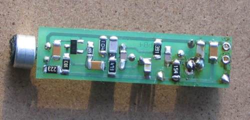
Before starting the assembly, it is important to have everything ready with the parts laid out on your workbench for easy identification. The surface mount capacitors are going to be the most difficult to identify as they don't have any markings and the size is no indication of the value. The only way to identify their value is the order in which they come in the carrier strip. Refer to the following diagram for the placement of the capacitors as well as the resistors: For a comprehensive guide to soldering surface-mount, read the article on this CD: "Soldering Surface Mount", and the construction notes for the Micro Bug, as these will give you further guidance and extra information. Fit all the surface-mount components first. Then the two transistors and coils. Make sure the enamel is scraped off the leads before fitting by using a sharp blade or file or sand paper. The most convenient way is to remove the enamel by applying a fair amount of solder to the iron tip and hold it to the wire until the enamel bubbles off, leaving the copper wire tinned. Don't squash the turns of the coil together as they may have to be stretched apart during testing, for setting the frequency. Now the board is now ready for the microphone, switch and batteries. You can solder directly to the button cells if you firstly scrape the top and bottom with a blade or file. This will roughen the surface so the solder will stick. Make sure the soldering is carried out very quickly otherwise the seals on the cells will be damaged and they will leak. These chemicals are very corrosive, so be careful. The microphone needs two short lengths of tinned copper wire soldered to its lands so it can be connected to the board. The microphone is polarized so it must be connected the correct way. The negative lead of the microphone goes to the case. The negative rail of the project is the copper strip that runs the length of the bottom of the board and meets the negative terminal of the battery. The microphone must be soldered very quickly otherwise the FET inside the case will be damaged and it will lose sensitivity and produce a lot of back-ground noise.
THE CASE
The only thing we haven't provided in the kit is the case. This has been left up to you as there are so many different types of pens and markers that will hold the project. It is preferable to use an old, dried out marker as this will save you a couple of dollars and you don't have to handle any messy ink. If you want the pen or marker to write normally so that no-one will suspect the contents, you will have to provide a section up the front to hold the pad of ink and this will have to be sectioned off from the rest of the barrel to prevent the ink drying out. The main aim is to get a case that will fit the board, batteries and switch. After this you can see how much room you have for the ink. Next you will have to work out the switch arrangement and it can be either a slide switch mounted inside, a pressure switch kept apart with a pin or a reed switch kept open with a magnet on the outside of the case. When the pin is pulled out or the magnet removed, the switch closes and the bug is activated. The Commercial bug (as explained the MkIl article) did not have a switch. Two button cells were fitted into the barrel and the cap screwed on. The bug was then active and would operate for about 8 hours. The idea is to arm the bug before-hand and leave it at a meeting etc. Later you can go back and pick it up. The bug we saw was actually a ball-point pen and the ink was contained in a refill near the tip. By the time we got it, the ink had run out and the only telltale difference was the larger-than-normal barrel and extra weight. Anyone with a fair degree of intelligence would become suspicious at the extra size and wonder why the pen is so cumbersome. You could not see the hole at the end for the microphone and no external antenna was used.
MEASURING THE OUTPUT
It is essential to be able to measure the output without physically touching any part of the circuit and this is why we use the Field Strength Meter. Coil a sheet of paper around the board and hold it in place with sticky tape. Coil the antenna wire on this paper former and space the turns. By adjusting the position of this antenna, you will be able to get the maximum output. Place the board inside a marker pen and finally test it for both range and clarity. When you are satisfied with the results, fit some small pieces of foam to prevent the board moving around and fit the pen tip. Now you are ready to try it out. Ask someone to use your “Pen” and see if they notice anything different. Don't let them know or they'll want one too!
PARTS LIST
1 - 390R (marked 391)
1 - 10k (marked 103)
1 - 22k (marked 223)
1 - 47k (marked 473)
2 - 100k (marked 104)
1 - 1M (marked 105)
1 - 4p7 surface mount
2 - 10p surface mount
1 - 47p surface mount
1 - 1n surface mount
2 - 22n surface mount
1 - 100n surface mount
1 - BC 547 transistor
1 - BC 848 transistor “ 1k ”
1 - 2N 3563 RF transistor
1 - electret microphone insert
20cm - enamelled wire
1 - ferrite core, F29 material
1 - 5 turn enamel wire coil, 3mm dia
3 - 1.5v Button cells
1 - mini slide switch SPDT
1 - 1.5m enamel wire for antenna
Related Links
Downloads
Pen FM Transmitter Bug - Link
|
|
|
| |
Accurate LC Meter
Build your own Accurate LC Meter (Capacitance Inductance Meter) and start making your own coils and inductors. This LC Meter allows to measure incredibly small inductances making it perfect tool for making all types of RF coils and inductors. LC Meter can measure inductances starting from 10nH - 1000nH, 1uH - 1000uH, 1mH - 100mH and capacitances from 0.1pF up to 900nF. The circuit includes an auto ranging as well as reset switch and produces very accurate and stable readings. |
|
PIC Volt Ampere Meter
Volt Ampere Meter measures voltage of 0-70V or 0-500V with 100mV resolution and current consumption 0-10A or more with 10mA resolution. The meter is a perfect addition to any power supply, battery chargers and other electronic projects where voltage and current must be monitored. The meter uses PIC16F876A microcontroller with 16x2 backlighted LCD. |
|
|
|
60MHz Frequency Meter / Counter
Frequency Meter / Counter measures frequency from 10Hz to 60MHz with 10Hz resolution. It is a very useful bench test equipment for testing and finding out the frequency of various devices with unknown frequency such as oscillators, radio receivers, transmitters, function generators, crystals, etc. |
|
1Hz - 2MHz XR2206 Function Generator
1Hz - 2MHz XR2206 Function Generator produces high quality sine, square and triangle waveforms of high-stability and accuracy. The output waveforms can be both amplitude and frequency modulated. Output of 1Hz - 2MHz XR2206 Function Generator can be connected directly to 60MHz Counter for setting precise frequency output. |
|
|
|
BA1404 HI-FI Stereo FM Transmitter
Be "On Air" with your own radio station! BA1404 HI-FI Stereo FM Transmitter broadcasts high quality stereo signal in 88MHz - 108MHz FM band. It can be connected to any type of stereo audio source such as iPod, Computer, Laptop, CD Player, Walkman, Television, Satellite Receiver, Tape Deck or other stereo system to transmit stereo sound with excellent clarity throughout your home, office, yard or camp ground. |
|
USB IO Board
USB IO Board is a tiny spectacular little development board / parallel port replacement featuring PIC18F2455/PIC18F2550 microcontroller. USB IO Board is compatible with Windows / Mac OSX / Linux computers. When attached to Windows IO board will show up as RS232 COM port. You can control 16 individual microcontroller I/O pins by sending simple serial commands. USB IO Board is self-powered by USB port and can provide up to 500mA for electronic projects. USB IO Board is breadboard compatible. |
|
|
|
|
ESR Meter / Capacitance / Inductance / Transistor Tester Kit
ESR Meter kit is an amazing multimeter that measures ESR values, capacitance (100pF - 20,000uF), inductance, resistance (0.1 Ohm - 20 MOhm), tests many different types of transistors such as NPN, PNP, FETs, MOSFETs, Thyristors, SCRs, Triacs and many types of diodes. It also analyzes transistor's characteristics such as voltage and gain. It is an irreplaceable tool for troubleshooting and repairing electronic equipment by determining performance and health of electrolytic capacitors. Unlike other ESR Meters that only measure ESR value this one measures capacitor's ESR value as well as its capacitance all at the same time. |
|
Audiophile Headphone Amplifier Kit
Audiophile headphone amplifier kit includes high quality audio grade components such as Burr Brown OPA2134 opamp, ALPS volume control potentiometer, Ti TLE2426 rail splitter, Ultra-Low ESR 220uF/25V Panasonic FM filtering capacitors, High quality WIMA input and decoupling capacitors and Vishay Dale resistors. 8-DIP machined IC socket allows to swap OPA2134 with many other dual opamp chips such as OPA2132, OPA2227, OPA2228, dual OPA132, OPA627, etc. Headphone amplifier is small enough to fit in Altoids tin box, and thanks to low power consumption may be supplied from a single 9V battery. |
|
|
|
|
|
Arduino Prototype Kit
Arduino Prototype is a spectacular development board fully compatible with Arduino Pro. It's breadboard compatible so it can be plugged into a breadboard for quick prototyping, and it has VCC & GND power pins available on both sides of PCB. It's small, power efficient, yet customizable through onboard 2 x 7 perfboard that can be used for connecting various sensors and connectors. Arduino Prototype uses all standard through-hole components for easy construction, two of which are hidden underneath IC socket. Board features 28-PIN DIP IC socket, user replaceable ATmega328 microcontroller flashed with Arduino bootloader, 16MHz crystal resonator and a reset switch. It has 14 digital input/output pins (0-13) of which 6 can be used as PWM outputs and 6 analog inputs (A0-A5). Arduino sketches are uploaded through any USB-Serial adapter connected to 6-PIN ICSP female header. Board is supplied by 2-5V voltage and may be powered by a battery such as Lithium Ion cell, two AA cells, external power supply or USB power adapter. |
|
200m 4-Channel 433MHz Wireless RF Remote Control
Having the ability to control various appliances inside or outside of your house wirelessly is a huge convenience, and can make your life much easier and fun. RF remote control provides long range of up to 200m / 650ft and can find many uses for controlling different devices, and it works even through the walls. You can control lights, fans, AC system, computer, printer, amplifier, robots, garage door, security systems, motor-driven curtains, motorized window blinds, door locks, sprinklers, motorized projection screens and anything else you can think of. |
|
|
|


