| |
This project uses a Microchip PIC microcontroller, a serial EEPROM and a thermistor to create a temperature recorder.
The temperature is measured and stored at user programmable intervals; this can be from 1 second to 256 seconds. The time interval is set by programming it and the start time into the EEPROM.
Most of the time the PIC will be asleep and the EEPROM IC is inactive. This gives a very low current consumption of approximately 50 uA or about 1 mAh per day.
The EEPROM used is 32kBytes which can store up to 32,000 measurements. This could be one measurement every 30 seconds for 11 days for example.
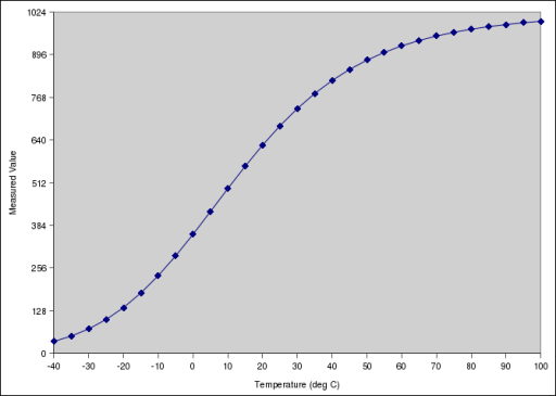
The combination of thermistor and analogue circuit gives a range of between about -40 °C and +100 °C although the linear range is between about -10 °C and +40 °C.

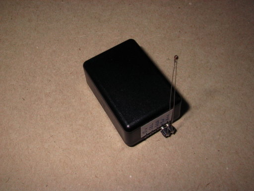
In this picture the temperature recorder can be seen with the external thermistor plugged in. The connector on the end contains power, I2C clock and data and analogue input.
The overall size of the complete unit is 40 mm long, 26 mm wide and 16 mm tall.
Box with battery pack
In this picture the temperature recorder is connected to a battery pack with 4xAAA batteries. This gives a good indication of the size and shows that I need a much smaller set of batteries.
PCB (version 1)
PCB version 1
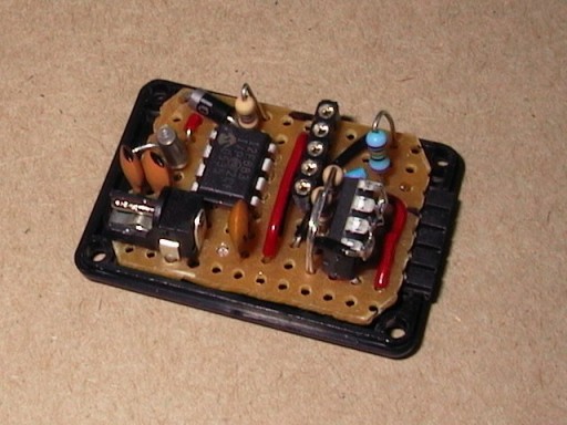
The first version of the circuit is built on stripboard with DIL packaged ICs and conventional through-hole passive components.
The PIC microcontroller is to the left of centre on the PCB with the EEPROM IC mounted vertically to save space on the right of centre.
The external connectors are the 1.3mm power socket on the bottom left and the 5 pin SIL socket on the right.
The other components are the ICSP socket with resistor and diode at the top left, crystal oscillator and two capacitors on the left of the PIC, the two I2C pull-up resistors next to the EEPROM and the resistor for the thermistor potential divider at the top right.
PCB (version 2)
PCB version 2
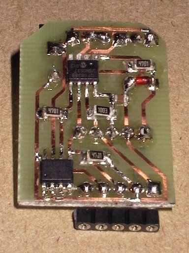
The second version of the circuit is built on a homemade single sided PCB with SO8 packaged ICs and surface mount passive components.
The ICs have a pitch of only 0.05" (1.27 mm), the decoupling capacitor is an 0805 package (0.08" by 0.05" = 2 mm x 1.27 mm) while the resistors are in a 1206 package (3 mm x 1.5 mm). The crystal and its capacitors are the same as before as are the connectors. The tracks are all routed with 0.02" width (0.5 mm) although in the final production they have come out slightly wider.
Software
PIC Software
The PIC software is written in assembler and based on earlier projects using I2C interfaces. The EEPROM, PIC and external connector all share the same I2C bus and the PIC will not use it unless the thermistor is fitted. The EEPROM address keeps incrementing in this case so that breaks in the data can be seen.
When the temperature measurement is not being made the PIC goes to sleep. It is woken once a second (using an external crystal oscillator and internal counter) to check if it is time to make a measurement. The sampling interval is stored in a fixed location in the external EEPROM and is read at power up.
The thermistor and a resistor form a potential divider that is measured by one of the ADC channels on the PIC. This is measured four times and the four results are added together. This gives a slightly better measurement since the average of four readings is likely to be closer to the true value than a single measurement alone due to the noise present in the circuit.
The ADC measurement is stored directly rather than being converted to a temperature first. To save space and maintain accuracy the change from the previous measurement is stored in 1 byte when possible, otherwise 2 bytes are used. If the value has changed from last time by between -112 and +112 then the amount of the change is stored. If the value has changed more than this then two bytes are stored with the first byte having flag bits to indicate this.
The PIC is a 12F683 device and runs at 4 MHz using the internal oscillator. The I2C interfaces run at nearly 100 kHz using bit-banging (programmed control of the I/O lines) and not a PIC SSP interface.
The complete information for this project is available for download. This includes the library functions for the I2C interface as well as the circuit diagram, layout diagram and various C programs. This project is included in the library of PIC code that is available for download.
PC Software
To reset the device there is a program that wipes the entire EEPROM (to 0xff) and writes a 32 byte header with the time and the sampling interval. The PIC will use the sampling interval to decide when to make a measurement and the start time is used by the program that extracts the data.
To read the data from the PIC there is software that dumps the entire EEPROM contents and extracts the start time, step size and raw data. The data is converted to date, time, measurement value and temperature for each data point in the EEPROM.
Circuit Diagram
Circuit Diagram
The circuit diagram is very simple with only the ADC interface (one resistor), I2C interface (2 resistors), EEPROM IC, ICSP (socket, 1 diode and 1 resistor), oscillator (crystal and 2 capacitors).
Circuit Layout version 1
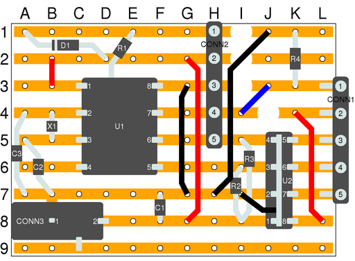
Circuit Layout on Stripboard
This simple PCB layout diagram shows the placement of the components on the stripboard. The view is from the top of the PCB, the same as in the photograph.
Circuit Layout version 2
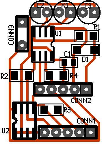
Circuit Layout on Custom PCB
This PCB layout diagram shows the components and the tracks on the custom PCB. The view of this PCB is from the side with the tracks although some of the components are mounted on the other side.
Components
None of the parts for this project are difficult to find although the surface mount components are less common than the standard ones.
Example Results
The image below shows an example of the results that can be obtained with this device.
Captured temperature data
The temperature logger was placed next to a household thermostat for a period of about 10 days in the winter at the start of 2007. On the plot are shown the measured temperature and the thermostat settings (an "intelligent" thermostat that aims to reach the target temperature at the specified time). The measured data clearly matches the thermostat setting for the time that the heating is active and during the day and night that it is inactive the temperature drops rapidly.


|
|
|
| |
Accurate LC Meter
Build your own Accurate LC Meter (Capacitance Inductance Meter) and start making your own coils and inductors. This LC Meter allows to measure incredibly small inductances making it perfect tool for making all types of RF coils and inductors. LC Meter can measure inductances starting from 10nH - 1000nH, 1uH - 1000uH, 1mH - 100mH and capacitances from 0.1pF up to 900nF. The circuit includes an auto ranging as well as reset switch and produces very accurate and stable readings. |
|
PIC Volt Ampere Meter
Volt Ampere Meter measures voltage of 0-70V or 0-500V with 100mV resolution and current consumption 0-10A or more with 10mA resolution. The meter is a perfect addition to any power supply, battery chargers and other electronic projects where voltage and current must be monitored. The meter uses PIC16F876A microcontroller with 16x2 backlighted LCD. |
|
|
|
60MHz Frequency Meter / Counter
Frequency Meter / Counter measures frequency from 10Hz to 60MHz with 10Hz resolution. It is a very useful bench test equipment for testing and finding out the frequency of various devices with unknown frequency such as oscillators, radio receivers, transmitters, function generators, crystals, etc. |
|
1Hz - 2MHz XR2206 Function Generator
1Hz - 2MHz XR2206 Function Generator produces high quality sine, square and triangle waveforms of high-stability and accuracy. The output waveforms can be both amplitude and frequency modulated. Output of 1Hz - 2MHz XR2206 Function Generator can be connected directly to 60MHz Counter for setting precise frequency output. |
|
|
|
BA1404 HI-FI Stereo FM Transmitter
Be "On Air" with your own radio station! BA1404 HI-FI Stereo FM Transmitter broadcasts high quality stereo signal in 88MHz - 108MHz FM band. It can be connected to any type of stereo audio source such as iPod, Computer, Laptop, CD Player, Walkman, Television, Satellite Receiver, Tape Deck or other stereo system to transmit stereo sound with excellent clarity throughout your home, office, yard or camp ground. |
|
USB IO Board
USB IO Board is a tiny spectacular little development board / parallel port replacement featuring PIC18F2455/PIC18F2550 microcontroller. USB IO Board is compatible with Windows / Mac OSX / Linux computers. When attached to Windows IO board will show up as RS232 COM port. You can control 16 individual microcontroller I/O pins by sending simple serial commands. USB IO Board is self-powered by USB port and can provide up to 500mA for electronic projects. USB IO Board is breadboard compatible. |
|
|
|
|
ESR Meter / Capacitance / Inductance / Transistor Tester Kit
ESR Meter kit is an amazing multimeter that measures ESR values, capacitance (100pF - 20,000uF), inductance, resistance (0.1 Ohm - 20 MOhm), tests many different types of transistors such as NPN, PNP, FETs, MOSFETs, Thyristors, SCRs, Triacs and many types of diodes. It also analyzes transistor's characteristics such as voltage and gain. It is an irreplaceable tool for troubleshooting and repairing electronic equipment by determining performance and health of electrolytic capacitors. Unlike other ESR Meters that only measure ESR value this one measures capacitor's ESR value as well as its capacitance all at the same time. |
|
Audiophile Headphone Amplifier Kit
Audiophile headphone amplifier kit includes high quality audio grade components such as Burr Brown OPA2134 opamp, ALPS volume control potentiometer, Ti TLE2426 rail splitter, Ultra-Low ESR 220uF/25V Panasonic FM filtering capacitors, High quality WIMA input and decoupling capacitors and Vishay Dale resistors. 8-DIP machined IC socket allows to swap OPA2134 with many other dual opamp chips such as OPA2132, OPA2227, OPA2228, dual OPA132, OPA627, etc. Headphone amplifier is small enough to fit in Altoids tin box, and thanks to low power consumption may be supplied from a single 9V battery. |
|
|
|
|
|
Arduino Prototype Kit
Arduino Prototype is a spectacular development board fully compatible with Arduino Pro. It's breadboard compatible so it can be plugged into a breadboard for quick prototyping, and it has VCC & GND power pins available on both sides of PCB. It's small, power efficient, yet customizable through onboard 2 x 7 perfboard that can be used for connecting various sensors and connectors. Arduino Prototype uses all standard through-hole components for easy construction, two of which are hidden underneath IC socket. Board features 28-PIN DIP IC socket, user replaceable ATmega328 microcontroller flashed with Arduino bootloader, 16MHz crystal resonator and a reset switch. It has 14 digital input/output pins (0-13) of which 6 can be used as PWM outputs and 6 analog inputs (A0-A5). Arduino sketches are uploaded through any USB-Serial adapter connected to 6-PIN ICSP female header. Board is supplied by 2-5V voltage and may be powered by a battery such as Lithium Ion cell, two AA cells, external power supply or USB power adapter. |
|
200m 4-Channel 433MHz Wireless RF Remote Control
Having the ability to control various appliances inside or outside of your house wirelessly is a huge convenience, and can make your life much easier and fun. RF remote control provides long range of up to 200m / 650ft and can find many uses for controlling different devices, and it works even through the walls. You can control lights, fans, AC system, computer, printer, amplifier, robots, garage door, security systems, motor-driven curtains, motorized window blinds, door locks, sprinklers, motorized projection screens and anything else you can think of. |
|
|
|