| |
Portable Tube Headphone Amp |
|
This little tube amplifier is easy to build and will fit into a small metal Altoids box and can be carried around. It can be build with few common parts, that should be readily available. Amplifier works with many tubes like 6DJ8, ECC88, 6922, 12AT7, 12AX7, DAF96, 1T4, etc. It is powered by 12V supply and power consumption may be optimized to allow for small rechargeable battery packs.

Explanation of the circuit
Basically, this is a grounded cathode voltage amp followed by an opamp buffer. For full understanding ignore the opamp stage and look at the tubed voltage amp. Just cut (in memory) the wire between the tube and the opamp (+) input. The triode is fixed-biased by the grid-charge current that flows through the 1meg resistor.
To explain this:
The hot cathode always emits some electrons that have enough energy to fly up to the grid. The grid resistor closes the current path between grid and cathode so that the grid discharges across the resistor and following Ohm´s law builds up a negative voltage between grid and cathode = ground. This way of biasing works for many small signal tubes like 6DJ8, ECC88, 6922 but also for 12AT7, 12AX7 etc.. It works for pentodes as well, like DAF96, 1T4. It won’t work for power tubes like 2A3 or so because the bias voltage is in the range of -0.3..-0.8VDC only.
Choosing the value of the grid resistor:
It´s written in the books. It is that value named “max. grid resistor†and often is combined with the type of bias: Automatic or fixed. Choose the value for “fixedâ€.
Here I have to correct myself:
If the book says “fixed bias†this is for an external negative voltage to be applied to the grid. If the book says “automatic bias†this is for the bias acquired by a cathode resistor. Most books don’t say anything about “grid-leakage bias†!!! If there is a value, use it. If not: Use the value for automatic bias and multiply it by 10. In my circuit the R1 value should be up to 10 megOhm. The circuit works ok for R1 = 1megOhm but one can be sure that there is a small amount of grid current flowing.
Choosing a plate resistor:
Normally you would take the value off the data book, too. But in this case it is not possible because the plate voltage is so low that no curves exist for most of the tubes. Here is a procedure how to get a value without curve-tracing. The plate resistor value is chosen that it will consume 4..6 V from the 12 V DC power. I recommend that this resistor is adjustable if you use any other tube than the 6DJ8 series or want to use other supply voltages. Always adjust the plate resistor to consume 1/2 to 1/3 of the supply voltage. If you try pentodes the plate resistor may consume up to 2/3 of the supply voltage. Start with a high value, up to 200kOhm, and adjust to lower while continuously measuring the voltage between plate and B+ until it fits. Now take the adjustable resistor off the circuit and measure the resistance. You now may choose the standard value nearest to the result of the measurement. An amplified input signal can now be seen at the opamp (+) input if we “repair†the wire we cut above.
The opamp in the prototype is an NJM4456 dual opamp. It is able to feed as much as 70mA into a 150 Ohm load.The NJM is not as “hot†as modern opamps with enormous high gain-bandwidth products. So it is not very likely that you will have problems with noise or oscillation.You may also try other opamps like NE5532 or OPA2134 or so. Make sure that they are “unity gain stableâ€. That means they will work flawlessly at a gain of 1.That´s the configuration we need. We wire the output to the negative input and feed the signal into the positive input. From the DC point of view this input sits at about 1/2 of the supply voltage, according how exactly you have chosen the plate resistor. In steady-state the output of the opamp follows the input (with a gain of 1 here)and therefore sits at 1/2 of the supply voltage, too.
Side note:
You could use a standard buffer like the BUF634, too. It is more expensive, provides even more current and you need two of those.The result is the same: The output follows the input and sits at 1/2 B+.Ok. Here is another correction:It was reported that the BUF634 would be outside a feedback loop and therefore is nearly uncontrollable. It may work or not…A better way is to put a MOSFET source follower as a buffer behind the opamp.We do not like to feed the headphones with DC, so we need to go with an output cap.Warning: Never go without output cap, otherwise your headphones (and probably your ears) will be ruined immediately.You may use an electrolytic of 220uF for cans above 32 Ohms, like the PortaPro or SportaPro. You should use 470uF for lo-Z headphones.Some people put a small film cap in parallel to the electrolytic to have better high frequency response.
Important: Watch the polarity of the cap. The + side of the cap goes toward the opamp output! Essential are the two resistors after the cap.
The bleeder resistor:
This one, to ground, will allow the cap to charge at power on. This helps to minimize the POP when you connect the headphones.
Side note:
You should connect / disconnect the headphones always if the amp is up and running. You won´t notice POPs and this helps to preserve the sound qualities of the headphones. The bleeder resistor should be about 10 times higher than the value of the headphone impedance plus the output resistor value.
The output resistor:
The output resistor is chosen between 22 and 150 Ohm depending on which final gain the amp should have.The output resistor forms a a voltage divider together with the headphone impedance.As a rule of thumb choose the low value for high-Z headphones (>=250 Ohm) and the high value for lo-Z headphones (32 Ohm). Changing the value of the output resistor has _some_ effect on the sound and the stability of the opamp stage.The NJM likes load impedance of 100 Ohm and higher best.
Feeding the heater:
This is done by an LM317T voltage regulator wired as constant current source. You only need one for two channels because the tube is a double triode, having two triode systems inside. Check the tube data: The 6DJ8 is fired with 300mA constant current or 6.3VDC constant voltage. We choose constant current. This is easy to achieve with the LM317 and an additional resistor. The current flowing is given by the formula:
I = 1.25 V / R, or solved for R:
R = 1.25V / I (desired_heater_current) = 1.25V / 0.3 A = 4.2 Ohm
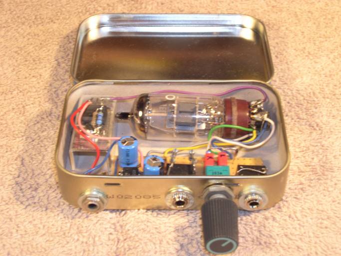
Construction detailsI am the least talented case builder under the sun so I always prefer readily available boxes.This one is an Altoids “Winter Green†tin. I guess it works with any of those Altoid tins.I don´t know if it works with Fisherman´s friends, too. I will test it if someone sends me a box of Penguin mints (hint, hint).
So here´s the look into the inside:
The tube socket was a standard bakelite chassis mount type. I had to “Dremelâ€-away some material to get it fit into the box.All resistors are standard 1/4 watt metal film types.The circuit diagram does not show the small Alps pot serving as a volume control. The value is 10kOhm but it may be as high as 100kOhm as well.You can leave it out if you have a volume control with your source.I use paralleled resistors to achieve the resistor value for the current source LM317T. You may use one resistor as well but be sure that it can consume at least 1 watt. The configuration of my amp is not bullet-proof. Because I use 1/4 watt resistors in parallel. They get really hot !The inside of the tin is covered with cardboard. This is really necessary because the LM317T has the output at heatsink and would be shorted to ground if touching bare metal.The layout itself is a bit messy, after all. I placed the components according to space optimization. I would be rather happy if somebody could provide a PCB layout.Building this amp was fun, but sometimes a drag because of the small enclosure.
Power supply
As you see 12VDC are necessary to power this amp. It consumes a little more than 300mA. You may use a batt pack of 10..12 NiCd or NiMh rechargables giving you about 5 hrs. of continuous listening if you choose 2000mAh cells. Or power it off your car battery if you go for a camping trip. Use a wall-wart at home, preferably a regulated and well filtered one. Try solar cells if you live in a sunny place.
How does it sound ?
Oh, well. After you had such a hard job to build this amp it is very unlikely that it sounds bad. The sound is mainly determined by the tube. It works at a very low plate voltage so that it probably produces a lot of distortion because the curves are far from being linear. There is a way to measure distortion using a PC-based tool. But I did not try. My PC soundcard is a lousy onboard chip with ugly noise from the computer. ps. So it really is a task someone else should perform. I think the distortion is of mainly even order, as characteristic for triodes. I experienced the sound being very warm, easy to listen to. Not that sterile as transistor amps and not as aggressive as some opamp based amps. I think the NJM and the 6DJ8 are good companions giving a nice and unfatiguing listening experience. This amp works fine with a large bandwidth of headphones. Maximum usable voltage is 4V(peak) and up to 70mA current which leads to a minimum load impedance of 53 Ohm. This is the absolute maximum and the amp will distort heavily. But I admit that I did not listen at that level. My oscilloscope and a dummy load did that for me.
Side note:
A 53 Ohm load impedance consists of the 22 Ohm output resistor in series with an about 30 Ohm dummy load. According to Ohms law this means the dummy only gets about 2 V(peak) of audio. Imagine this going into your Sennheiser PX200 and you will know what LOUD means.

Related Links
Downloads
Portable Tube Headphone Amp - Link
|
|
|
| |
Accurate LC Meter
Build your own Accurate LC Meter (Capacitance Inductance Meter) and start making your own coils and inductors. This LC Meter allows to measure incredibly small inductances making it perfect tool for making all types of RF coils and inductors. LC Meter can measure inductances starting from 10nH - 1000nH, 1uH - 1000uH, 1mH - 100mH and capacitances from 0.1pF up to 900nF. The circuit includes an auto ranging as well as reset switch and produces very accurate and stable readings. |
|
PIC Volt Ampere Meter
Volt Ampere Meter measures voltage of 0-70V or 0-500V with 100mV resolution and current consumption 0-10A or more with 10mA resolution. The meter is a perfect addition to any power supply, battery chargers and other electronic projects where voltage and current must be monitored. The meter uses PIC16F876A microcontroller with 16x2 backlighted LCD. |
|
|
|
60MHz Frequency Meter / Counter
Frequency Meter / Counter measures frequency from 10Hz to 60MHz with 10Hz resolution. It is a very useful bench test equipment for testing and finding out the frequency of various devices with unknown frequency such as oscillators, radio receivers, transmitters, function generators, crystals, etc. |
|
1Hz - 2MHz XR2206 Function Generator
1Hz - 2MHz XR2206 Function Generator produces high quality sine, square and triangle waveforms of high-stability and accuracy. The output waveforms can be both amplitude and frequency modulated. Output of 1Hz - 2MHz XR2206 Function Generator can be connected directly to 60MHz Counter for setting precise frequency output. |
|
|
|
BA1404 HI-FI Stereo FM Transmitter
Be "On Air" with your own radio station! BA1404 HI-FI Stereo FM Transmitter broadcasts high quality stereo signal in 88MHz - 108MHz FM band. It can be connected to any type of stereo audio source such as iPod, Computer, Laptop, CD Player, Walkman, Television, Satellite Receiver, Tape Deck or other stereo system to transmit stereo sound with excellent clarity throughout your home, office, yard or camp ground. |
|
USB IO Board
USB IO Board is a tiny spectacular little development board / parallel port replacement featuring PIC18F2455/PIC18F2550 microcontroller. USB IO Board is compatible with Windows / Mac OSX / Linux computers. When attached to Windows IO board will show up as RS232 COM port. You can control 16 individual microcontroller I/O pins by sending simple serial commands. USB IO Board is self-powered by USB port and can provide up to 500mA for electronic projects. USB IO Board is breadboard compatible. |
|
|
|
|
ESR Meter / Capacitance / Inductance / Transistor Tester Kit
ESR Meter kit is an amazing multimeter that measures ESR values, capacitance (100pF - 20,000uF), inductance, resistance (0.1 Ohm - 20 MOhm), tests many different types of transistors such as NPN, PNP, FETs, MOSFETs, Thyristors, SCRs, Triacs and many types of diodes. It also analyzes transistor's characteristics such as voltage and gain. It is an irreplaceable tool for troubleshooting and repairing electronic equipment by determining performance and health of electrolytic capacitors. Unlike other ESR Meters that only measure ESR value this one measures capacitor's ESR value as well as its capacitance all at the same time. |
|
Audiophile Headphone Amplifier Kit
Audiophile headphone amplifier kit includes high quality audio grade components such as Burr Brown OPA2134 opamp, ALPS volume control potentiometer, Ti TLE2426 rail splitter, Ultra-Low ESR 220uF/25V Panasonic FM filtering capacitors, High quality WIMA input and decoupling capacitors and Vishay Dale resistors. 8-DIP machined IC socket allows to swap OPA2134 with many other dual opamp chips such as OPA2132, OPA2227, OPA2228, dual OPA132, OPA627, etc. Headphone amplifier is small enough to fit in Altoids tin box, and thanks to low power consumption may be supplied from a single 9V battery. |
|
|
|
|
|
Arduino Prototype Kit
Arduino Prototype is a spectacular development board fully compatible with Arduino Pro. It's breadboard compatible so it can be plugged into a breadboard for quick prototyping, and it has VCC & GND power pins available on both sides of PCB. It's small, power efficient, yet customizable through onboard 2 x 7 perfboard that can be used for connecting various sensors and connectors. Arduino Prototype uses all standard through-hole components for easy construction, two of which are hidden underneath IC socket. Board features 28-PIN DIP IC socket, user replaceable ATmega328 microcontroller flashed with Arduino bootloader, 16MHz crystal resonator and a reset switch. It has 14 digital input/output pins (0-13) of which 6 can be used as PWM outputs and 6 analog inputs (A0-A5). Arduino sketches are uploaded through any USB-Serial adapter connected to 6-PIN ICSP female header. Board is supplied by 2-5V voltage and may be powered by a battery such as Lithium Ion cell, two AA cells, external power supply or USB power adapter. |
|
200m 4-Channel 433MHz Wireless RF Remote Control
Having the ability to control various appliances inside or outside of your house wirelessly is a huge convenience, and can make your life much easier and fun. RF remote control provides long range of up to 200m / 650ft and can find many uses for controlling different devices, and it works even through the walls. You can control lights, fans, AC system, computer, printer, amplifier, robots, garage door, security systems, motor-driven curtains, motorized window blinds, door locks, sprinklers, motorized projection screens and anything else you can think of. |
|
|
|