| |
Repairing Switching Power Supply |
|
Modern power supplies are known as "switching regulator power supplies."
In most switching supplies, the 110 volt AC input is first rectified by
two diodes and filtered by a pair of capacitors. This creates two high-
voltage sources; one positive and the other negative.
A pair of transistors is then used to switch these high voltage supplies
across the primary winding of a transformer. This switching action is
very fast. A typical switching speed is around 40,000 cycles per second
or 40KHz. An integrated circuit is commonly used to control the
transistors. This IC not only controls the speed at which the
transistors are switched, but also controls the amount of time that each
transistor is energized. The output voltage of the power supply is
determined by the "on" time of the transistors. If the transistors are
keep on for a longer period of time, the output voltage of the supply
will rise, while shorter times lower the output voltage. This is known
as "pulse-width modulation."
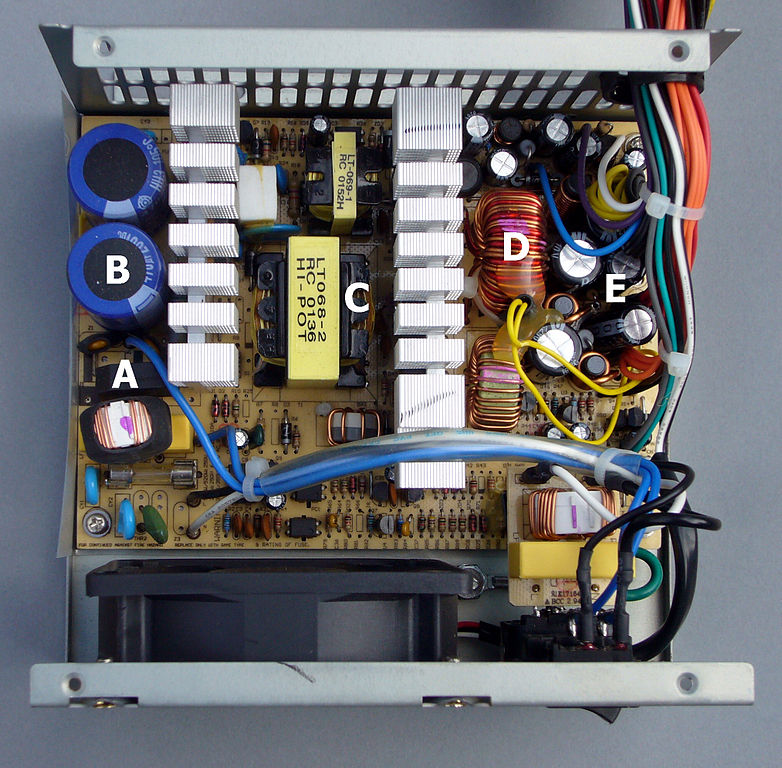
ATX power supply interior Legend:
A - bridge rectifier
B - input filter capacitors
between B and C - Heatsink of high-voltage transistors
C - transformer
between C and D - Heatsink of low-voltage, high-current rectifiers
D - output filter coil
E - output filter capacitors
The output of the transformer (which is now alternating current) is then rectified by special high-speed diodes to change it back to direct current. This output is not pure DC however, and requires extensive filtering to remove the high-frequency "noise" that is generated by the rapid switching action of the transistors. Filtering is accomplished by using a combination of coils (also known as "chokes") and capacitors.
The output voltage of the power supply is regulated by feeding some of the output back to the integrated circuit that controls the switching transistors. If the output voltage is too low, the IC allows the transistors to remain energized for a longer period of time, raising the voltage. An output voltage that is too high signals the IC to cut back on the transistors, lowering the output voltage.
Power Supply Failures
I have found that there are only a small handful of components that fail in switching regulator power supplies. The most common failure is the switching transistors themselves. The transistors short-circuit, causing massive amounts of current to be drawn across the transformer and blowing the fuse.
Transistor failure is often caused by bad capacitors. It is extremely common to find output filter capacitors that are swollen or leaking. Any capacitor that appears to be bad should be replaced. To prevent a recurrence of this all-to-common failure, output filter capacitors should be replaced with special "low ESR" (Equivalent Series Resistance) capacitors. These capacitors are specifically designed to handle the rigors of filtering in a switching supply. Most power supply manufacturers do not install low ESR capacitors as original equipment because they are somewhat more expensive that conventional capacitors. However, it is well worth the money to use them as replacement components as they will greatly extend the life of the power supply in the field. When I work on a power supply, I replace all the output filter capacitors with low ESR caps regardless of whether they appear to be good or bad. Since a service call costs far more than the capacitors, it's a prudent thing to do.
Diode failure is another common problem. There are quite a few diodes in a switching supply and failure of any one of them will cause the supply to blow the fuse or shut down. The most common diode failures are shorted +12 volt or -5 volt output rectifiers. Failure of these diodes will not blow the fuse. The supply simply detects the short and shuts itself down. Some of these failures may be caused by using the +12 or -5 volt outputs to power coin door lamps. The -5 volt output is not over- current protected in all power supplies. A shorted lamp socket may blow the diode by drawing too much current from the supply. The +12 volt diodes may be blown if 6 volt bulbs are inadvertently used instead of 12 volt bulbs. The high-voltage input diodes may also short-circuit. This is often accompanied by shorted switching transistors and will blow the fuse.
Testing and Repair
All testing is done with the power off. Start by testing the pair of switching transistors. These will be mounted on a heatsink that helps them run cooler. Test them by using an ohmeter or a digital multimeter set to the diode test range. Check each transistor for a short between emitter and collector. Replace any transistors you find to be bad. Although some technicians claim that you should replace them both even if just one is bad, I have not found this to be necessary.
By the way, these transistors will always seem to test shorted between base and emitter when tested "in-circuit." I generally don't bother testing the base-emitter junction of the transistors. When the switching transistors fail, they always short between emitter and collector. If you're in doubt, pull the transistors out of circuit to test them. If the transistors are shorted, the fuse will have blown. Be sure to test the high-voltage diodes as well. The high-voltage diodes are usually part of a bridge rectifier, although they may be individual diodes.
Next, test the output rectifiers. There are three pairs of diodes to test. One pair is for the -5 volt output. These will be fairly small; approximately the same size as the ubiquitous 1N4004 with which we are all familiar. The +12 volt diodes are usually somewhat larger. The two +5 volt output diodes are housed together in a "dual-diode" package that looks very much like a transistor. Like the switching transistors, this diode package is mounted on a heatsink. It will generally have the diode schematic symbols printed on it. This diode will usually not test properly in-circuit. Testing can be simplified by unsoldering it with a "solder sucker" instead of removing it completely from the printed circuit board. I have seen very few failures of the +5 volt output diodes. All diodes must be replaced with high-speed diodes or the power supply will generate excessive noise.
Follow these tests by replacing all the output capacitors with low ESR caps and fire up the power supply. The supply should be tested under load. Use a 1 ohm, 50 watt resistor or equivalent as a "dummy load", connected between the +5 volt output and ground (DC COM). This will draw 5 amps from the supply, which is adequate for test purposes. If the supply is still inoperative, the integrated circuit may be bad. Test the IC by removing it from the printed circuit board and installing it in a power supply that you know to be good. I have a spare power supply with a socket in it that I use exclusively to test integrated circuits. Just about all the supplies use the same IC; a type 494. Equivalent integrated circuits are: TL494CN, uA494, uPC494C, IR3MO2, and MB3759. The over-the-counter replacement for these is ECG1729.
Obtaining Replacement Components
One of the main arguments for tossing bad power supplies in the trash has been that the cost of the replacement components is almost equal to the cost of a new supply. That's just not true. The switching transistors are available for around $.90 each.
Most of the time you can tell that capacitor is bad just by looking at it's top surface. If it's bulged at the top it is bad and should to be replaced right away. Sometimes capacitors that look fine may be bad too and to identify these you will need to use ESR Meter. The capacitors you want to order are made by Nichicon. Order 3300 microfarad at 16 volts (part number UVX1C332M) and 1000 microfarad at 25 volts (part number UVX1E102M.) These will be suitable as replacements for output filter capacitors in virtually all makes and models of power supplies. Remember, you can always substitute a capacitor of higher voltage when replacing filter capacitors. E.G. A 1000 microfarad, 16 volt capacitor can be replaced with a 1000 microfarad, 25 volt.
Minus 5 Volt Output Too High
Most switching regulator power supplies have three DC outputs. One is the main +5 volt DC output that powers the computer system. The others are the +12 and -5 volt outputs. These DC outputs are often used to power the sound generating system and the audio amplifier itself. When you're testing a power supply, it's important to check all three of the outputs. This is especially true when you have a game that basically works okay but has distorted or missing audio.
When a switching regulator power supply fails, all three outputs will usually drop to zero volts. Sometimes, however, the output voltage may rise. If you find that the +5 VDC and +12 VDC outputs are normal but the -5 VDC output is too high (more than -6 VDC), try replacing the -5 output filter choke.
It's easy to locate the -5 volt filter choke, even without a schematic diagram. Just follow the trace on the printed circuit board back from the -5 VDC output of the power supply. You will eventually come to a component that may look something like a capacitor but will be clearly labeled "L" on the board and will generally be accompanied by the schematic symbol for a coil as well. The coil is wound on a ferrite coil and is covered with a plastic sleeve that has been heat-shrinked over it. Examine the coil. If the heat-shrinked cover has been melted or is missing entirely, the coil may be bad.
There are a couple of options for obtaining a replacement coil. The preferred method is to take the coil off a junk power supply. Alternately, you can pull the burned wire off the ferrite core and rewind the choke yourself using the appropriate gauge wire. There aren't that many turns of wire on it that you can't rewind a new coil in five minutes.
Output Capacitor Replacements
I have received a number of calls and letters from operators and technicians that are having trouble obtaining replacement capacitors for switching regulator power supplies. I recommend using Nichicon brand capacitors. I have been using them for almost two years and to date I have not seen a repeat capacitor failure.
I recommend that you order just two different Nichicon brand capacitors for use as replacements for the output filter capacitors. It helps a great deal when you have the part numbers. For the +5 VDC output, use 3300 microfarad, 16 VDC capacitors. The Nichicon part number is UVX1C332M. Each power supply requires two of these.
To make ordering and stocking easier, I use the same capacitor for both the +12 VDC and the -5 VDC outputs. It's a 1000 microfarad, 25 volt capacitor. The Nichicon part number is UVX1E102M. Although some power supplies use a 2200 microfarad capacitor for the +12 VDC output, I have found the 1000 microfarad to be perfectly satisfactory. Most power supplies use one capacitor each for the +12 VDC and -5 VDC outputs so order the same number of 1000 microfarad capacitors as you do the 3300 microfarad capacitors. When you replace the output filter capacitors, it's a good idea to change them all at once.
Output Diode Replacements
Output diodes are a common failure item in the switching regulator power supply. I would say that around twenty-five to thirty percent of them have bad output diodes.
High Speed Diodes
There are three pairs of output diodes; one pair for each of the outputs: +5 VDC, +12 VDC, and -5 VDC. These are not ordinary diodes. They are special, high-speed, "fast-recovery" diodes. High speed diodes are made to handle the very fast switching action (around 40 thousand cycles per second) of the power supply.
I have rarely replaced the +5 volt diode assembly in a switching regulator power supply. The +12 and -5 volt output diodes are the most common failures. It is normal for these diodes to test bad when checking them "in-circuit." There is usually a low ohm resistor (normally around 100 ohms) across the output of the power supply that causes a very low reading when checking the +12 or -5 volt output diodes. Most people unsolder and remove one end of each diode to test it but you can usually bypass this step. When these diodes fail they will generally short completely. Instead of reading around 100 ohms, you will get a reading of around zero ohms; a dead short!
Substitute Diodes
The +12 volt output diodes will usually carry an original part number like PXPR302 or FR302. These are 3 amp diodes. The -5 volt output diodes will often be type PXPR1502 or similar. Good engineering practice dictates that high speed, "fast-recovery" diodes be used in this circuit. I have found normal diodes will fail prematurely and as such are unacceptable as substitutions. The more you work on repairing power supplies, the easier it gets. When you consider that many power supply repairs are effected with the replacement of a single diode, you can see that they are anything but disposable!
Bad switching power supplies tend to fall into some categories:
1. Dead & silent with fuse blown
2. Dead & silent with fuse good
3. Dead & chirping/clicking with fuse good
4. Voltage output is OK but game acts goofy on this supply
#2 is the hardest to fix.
Switching power supplies run like this:
High voltage side: Brute force rectification of the mains voltage through a set of diodes - either separate ones or a 4 leaded bridge rectifier. This is filtered through a capacitor & goes to the switching circuit (after being stepped down through other components) and to the main switching transistor. Problems in here are related to #1 and are fairly easy to fix.
Regulation: this circuitry kicks off the supply & makes sure the output is correct. It runs the oscillation of the main switching transistor and monitors the output of the high frequency stepdown transformer through a feedback mechanism. Problems in here are related to #2 - the hard one to fix.
Low voltage side: Here are the rectifier diodes, filter choke coils, and capacitors that turn that high frequency AC output from the transformer into the DC output that is needed by the game. There's a small part of the circuitry here that gives the feedback to the regulation circutry to keep things running stable. Problems here are related to #3 and #4.
DISCLAIMER: *ALL* listed methods of troubleshooting are done with the power OFF. Keep in mind that problems listed as #2, #3, and #4 are related to things where the fuse is GOOD and the high voltage section of the board may have a charge on the large filter capacitors. Some power supplies have bleeder resistors across them. Others do NOT. Use a 150k 1/2w resistor to bleed those caps & test the voltage with your meter to keep yourself from getting a nasty shock. DC makes your muscles contract and if you pick up a power supply you might find yourself unable to let go. Yes - I have had this happen to me once. Take the proper precautions. That's how I learned that not all power supplies have bleeder resistors for those main filter caps on the high voltage side. Damn Apple II power supplies...
Fixing high voltage side:
Use your ohmmeter and check the resistance across all combinations of the 4 legs of the bridge rectifier. They should NOT read zero ohms. If they do, reverse the leads and check again... if they do... replace the component.
Do the same test across the legs of the main switching transistor and any other semiconductor (diode/transistor) in the high voltage section. Replace any shorted components.
Be aware that some switching supplies use low value resistors around the switching transistor. If you read around 2 ohms then you may be reading those. A shorted component is usually 1/2 ohm or less.
If you find shorted components anywhere in the high voltage section you should check the resistors for any open ones and replace as necessary. Replace the fuse, fix any cracked solder joints, reassemble, and test...
Fixing the low voltage side: Chirping supplies generally mean problems with the output. It could be a problem with the regulation portion too but I've never seen that as the case myself. Every case of chirping supplies I've worked on ended up having a shorted rectifier diode in the low voltage section.
Some of the diodes are dual-diodes that look like transistors. Look at the circuit board as most of them are labeled as "D#" or "CR#". Test these components with the ohmmeter and look for one that reads shorted both ways. It is common for the high speed dual rectifiers to read very low resistance one way - almost shorted looking - but they will read high the other way unless they are shorted.
Replace any shorted rectifiers, fix any cracked solder joints, reassemble, and test.
Power Supply works, but the game is flakey on it: Check the filter capacitors on the output section of the power supply. Look for ones that have split tops or ones that have tilted over or lifted up because the rubber plug has popped out of the bottom. If they all look OK then either shotgun them or check the outputs with an oscilloscope and look for trash high frequency AC ripple on them. Replace the caps as necessary to clean up those outputs, fix any cracked solder joint, reassemble, and test.
Problem in the regulation section: Well, these can be hard to figure out. The only times I've been successful at fixing these without a schematic (which isn't very often since you cannot usually get schematics for these) is when shotgunning the caps in the regulation section or finding a cracked solder joint.
What if I have a problem related to #1 or #3 and can't find a shorted component? Well, this gets trickier. Sometimes a semiconductor doesn't short out. Sometimes it gets "leaky" meaning the forward resistance is low like normal but the reverse path resistance is lower than it should be. When you run into these situations then check the components carefully. If you find one that is low one way and around 500 to 1000 or so ohms (maybe a little more, maybe a little less) then desolder one leg of the part, lift that leg out of the board and test the part out of circuit. If it reads low one way and not high the other (should be tens if not hundreds of thousands of ohms or higher the other way) then replace it as it may be leaky.
I've fixed hundreds of switching supplies over the years - Apple II and older Mac II, SE, SE/30, and lots of PC clone ones. I've also repaired them for various pieces of network gear. Keep the safety precautions in mind and make sure the caps are discharged and you should be safe.


Related Links
Downloads
Repairing Switching Power Supply - Link
|
|
|
| |
Accurate LC Meter
Build your own Accurate LC Meter (Capacitance Inductance Meter) and start making your own coils and inductors. This LC Meter allows to measure incredibly small inductances making it perfect tool for making all types of RF coils and inductors. LC Meter can measure inductances starting from 10nH - 1000nH, 1uH - 1000uH, 1mH - 100mH and capacitances from 0.1pF up to 900nF. The circuit includes an auto ranging as well as reset switch and produces very accurate and stable readings. |
|
PIC Volt Ampere Meter
Volt Ampere Meter measures voltage of 0-70V or 0-500V with 100mV resolution and current consumption 0-10A or more with 10mA resolution. The meter is a perfect addition to any power supply, battery chargers and other electronic projects where voltage and current must be monitored. The meter uses PIC16F876A microcontroller with 16x2 backlighted LCD. |
|
|
|
60MHz Frequency Meter / Counter
Frequency Meter / Counter measures frequency from 10Hz to 60MHz with 10Hz resolution. It is a very useful bench test equipment for testing and finding out the frequency of various devices with unknown frequency such as oscillators, radio receivers, transmitters, function generators, crystals, etc. |
|
1Hz - 2MHz XR2206 Function Generator
1Hz - 2MHz XR2206 Function Generator produces high quality sine, square and triangle waveforms of high-stability and accuracy. The output waveforms can be both amplitude and frequency modulated. Output of 1Hz - 2MHz XR2206 Function Generator can be connected directly to 60MHz Counter for setting precise frequency output. |
|
|
|
BA1404 HI-FI Stereo FM Transmitter
Be "On Air" with your own radio station! BA1404 HI-FI Stereo FM Transmitter broadcasts high quality stereo signal in 88MHz - 108MHz FM band. It can be connected to any type of stereo audio source such as iPod, Computer, Laptop, CD Player, Walkman, Television, Satellite Receiver, Tape Deck or other stereo system to transmit stereo sound with excellent clarity throughout your home, office, yard or camp ground. |
|
USB IO Board
USB IO Board is a tiny spectacular little development board / parallel port replacement featuring PIC18F2455/PIC18F2550 microcontroller. USB IO Board is compatible with Windows / Mac OSX / Linux computers. When attached to Windows IO board will show up as RS232 COM port. You can control 16 individual microcontroller I/O pins by sending simple serial commands. USB IO Board is self-powered by USB port and can provide up to 500mA for electronic projects. USB IO Board is breadboard compatible. |
|
|
|
|
ESR Meter / Capacitance / Inductance / Transistor Tester Kit
ESR Meter kit is an amazing multimeter that measures ESR values, capacitance (100pF - 20,000uF), inductance, resistance (0.1 Ohm - 20 MOhm), tests many different types of transistors such as NPN, PNP, FETs, MOSFETs, Thyristors, SCRs, Triacs and many types of diodes. It also analyzes transistor's characteristics such as voltage and gain. It is an irreplaceable tool for troubleshooting and repairing electronic equipment by determining performance and health of electrolytic capacitors. Unlike other ESR Meters that only measure ESR value this one measures capacitor's ESR value as well as its capacitance all at the same time. |
|
Audiophile Headphone Amplifier Kit
Audiophile headphone amplifier kit includes high quality audio grade components such as Burr Brown OPA2134 opamp, ALPS volume control potentiometer, Ti TLE2426 rail splitter, Ultra-Low ESR 220uF/25V Panasonic FM filtering capacitors, High quality WIMA input and decoupling capacitors and Vishay Dale resistors. 8-DIP machined IC socket allows to swap OPA2134 with many other dual opamp chips such as OPA2132, OPA2227, OPA2228, dual OPA132, OPA627, etc. Headphone amplifier is small enough to fit in Altoids tin box, and thanks to low power consumption may be supplied from a single 9V battery. |
|
|
|
|
|
Arduino Prototype Kit
Arduino Prototype is a spectacular development board fully compatible with Arduino Pro. It's breadboard compatible so it can be plugged into a breadboard for quick prototyping, and it has VCC & GND power pins available on both sides of PCB. It's small, power efficient, yet customizable through onboard 2 x 7 perfboard that can be used for connecting various sensors and connectors. Arduino Prototype uses all standard through-hole components for easy construction, two of which are hidden underneath IC socket. Board features 28-PIN DIP IC socket, user replaceable ATmega328 microcontroller flashed with Arduino bootloader, 16MHz crystal resonator and a reset switch. It has 14 digital input/output pins (0-13) of which 6 can be used as PWM outputs and 6 analog inputs (A0-A5). Arduino sketches are uploaded through any USB-Serial adapter connected to 6-PIN ICSP female header. Board is supplied by 2-5V voltage and may be powered by a battery such as Lithium Ion cell, two AA cells, external power supply or USB power adapter. |
|
200m 4-Channel 433MHz Wireless RF Remote Control
Having the ability to control various appliances inside or outside of your house wirelessly is a huge convenience, and can make your life much easier and fun. RF remote control provides long range of up to 200m / 650ft and can find many uses for controlling different devices, and it works even through the walls. You can control lights, fans, AC system, computer, printer, amplifier, robots, garage door, security systems, motor-driven curtains, motorized window blinds, door locks, sprinklers, motorized projection screens and anything else you can think of. |
|
|
|