| |
Simple Coil Less FM Transmitter |
|
For months I’ve been looking for a simple FM BUG project, the ones online require inductors which you either have to acquire or build, if you don’t have a LCR meter it becomes rather hard to get the circuit working, specially if you’re a beginner without an oscilloscope! – Sometimes they don’t even tell you which inductance is required and you have to calculate an estimate, which is the main reason why many high frequency RF projects fail in the first place. This circuit on the other hand performs pretty well, even if you’re manipulating the board or touching the coax it will stay within the tuned frequency (unless you touch the transistor or timing capacitor!).

From all the projects out there I’ve only seen one which didn’t require an external inductor since it simply used a pcb / trace inductor, however the board was big and the circuit itself had lots of stability issues, etc. I wasn’t going to waste my time with it.
My first FM BUG was based on one of the many schematics out there, it seldom worked. It was microphonic (due to the air core inductor) but the electret capsule itself did not modulate the output at all, needless to say it was very unstable and it never worked properly.
No surprises there, it’s very similar to other schematics so therefore I won’t go into the working details. Actually I might argue this one is a bit on the low efficiency side, but at the moment I don’t have the equipment to further improve it’s design.
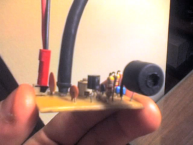
But let’s not focus on that and instead let’s talk about the inductor / antenna, it’s based on a 12cm long 50-75Ohms coaxial cable with one of it’s ends soldered (mesh and core are joined together) this is a big plus, we don’t have to use a flimsy air core inductor and we don’t need a lengthy wire antenna either – Great!
This tiny ghetto transmitter is guaranteed to work first time, as long as you double check all connections and you make sure your transistor is properly placed and in working order. I used the BF199 because it’s got a low capacitance and it’s ideal for this type of application, but you may use a 2n2222 or similar general purpose NPN BJT. I know, the schematic calls for a BF259 which is what I used in my simulation, but believe me it works beautifully with the BF199.
I didn’t have a 8.2pF capacitor so I used a smaller one, which naturally led the transmitter to work on the upper FM broadcast band, but hey — better than nothing!
The sound quality is not the best, this FM Bug could clearly benefit from an audio amplification stage. Another idea would be to scrap the electret and use an mp3 player instead. I reckon R4 could be ignored in that case but you might want to use a resistor in series with the input capacitor.
Another important component is the variable capacitor which forms the tuning circuit, I used a 4.5-20pF trimmer type capacitor, it’s the first one I found in the junk box, it was a bit flimsy and it required lots of patience to tune but I eventually got it to the point I wanted.
I recommend you get a ceramic screwdriver for the tuning or you can improvise one with a piece of plastic, it’s important because otherwise your body capacitance will affect the transmitter!
For those interested I also included the PCB layout, it’s very easy to etch your own PCBs so you should definitely give it a try! – Remember to keep the component leads to a minimum, we’re working with high frequencies, any parasitic capacitance, etc. will modify the behaviour of the circuit one way or another!
Click here to download all pertinent files for this project: fmbug_docs. The exports are not in perfect quality due to the PDF printer driver I used, but hey at least I’m providing the PCB layout, other projects leave this as an “exercise for the reader” (that’s because they never actually built the damn thing!)
One improvement over the current layout would be to get rid of the header for the power connection and use a button cell with a holder instead, another one would be to use a 3.5mm connector instead of the electret being soldered directly to the board.
And in case you’re wondering, here’s the BOM:
1x BF199 or similar RF NPN BJT.
1x 8.2pF Capacitor.
1x 2.2nF Capacitor.
1x 0.1uF Capacitor.
1x 50nF Capacitor.
1x 100 ohm resistor.
2x 4.7k resistor.
1x 5.6k resistor.
1x 3-30pF variable capacitor.
1x 3V source (I used 2x 1.5V AAs with a battery holder).
1x 12cm long piece of 50-75Ohms coaxial cable to serve as the inductor/antenna.
1x electret microphone (double check the polarity!)
Standby power consumption is ~5mA. During normal operation you should expect peaks of 10mA but on average 6mA is about right. L1 would be lucky to see peaks higher than 15mW!
If you want to increase the transmission distances you may use a metallic enclosure and solder the negative of the battery to the enclosure itself.
Also keep in mind my design was not meant to be used as a concealed spy bug, if you really wanted to build a proper spy bug you’d have to use SMT parts, these are generally not available to the beginner and therefore I went with through-hole components instead. Plus I’m against spying people without their consent…
That’s all for now, hopefully you’ll build and enjoy this tiny FM BUG.
Related Links
Downloads
Simple Coil Less FM Transmitter - Link
|
|
|
| |
Accurate LC Meter
Build your own Accurate LC Meter (Capacitance Inductance Meter) and start making your own coils and inductors. This LC Meter allows to measure incredibly small inductances making it perfect tool for making all types of RF coils and inductors. LC Meter can measure inductances starting from 10nH - 1000nH, 1uH - 1000uH, 1mH - 100mH and capacitances from 0.1pF up to 900nF. The circuit includes an auto ranging as well as reset switch and produces very accurate and stable readings. |
|
PIC Volt Ampere Meter
Volt Ampere Meter measures voltage of 0-70V or 0-500V with 100mV resolution and current consumption 0-10A or more with 10mA resolution. The meter is a perfect addition to any power supply, battery chargers and other electronic projects where voltage and current must be monitored. The meter uses PIC16F876A microcontroller with 16x2 backlighted LCD. |
|
|
|
60MHz Frequency Meter / Counter
Frequency Meter / Counter measures frequency from 10Hz to 60MHz with 10Hz resolution. It is a very useful bench test equipment for testing and finding out the frequency of various devices with unknown frequency such as oscillators, radio receivers, transmitters, function generators, crystals, etc. |
|
1Hz - 2MHz XR2206 Function Generator
1Hz - 2MHz XR2206 Function Generator produces high quality sine, square and triangle waveforms of high-stability and accuracy. The output waveforms can be both amplitude and frequency modulated. Output of 1Hz - 2MHz XR2206 Function Generator can be connected directly to 60MHz Counter for setting precise frequency output. |
|
|
|
BA1404 HI-FI Stereo FM Transmitter
Be "On Air" with your own radio station! BA1404 HI-FI Stereo FM Transmitter broadcasts high quality stereo signal in 88MHz - 108MHz FM band. It can be connected to any type of stereo audio source such as iPod, Computer, Laptop, CD Player, Walkman, Television, Satellite Receiver, Tape Deck or other stereo system to transmit stereo sound with excellent clarity throughout your home, office, yard or camp ground. |
|
USB IO Board
USB IO Board is a tiny spectacular little development board / parallel port replacement featuring PIC18F2455/PIC18F2550 microcontroller. USB IO Board is compatible with Windows / Mac OSX / Linux computers. When attached to Windows IO board will show up as RS232 COM port. You can control 16 individual microcontroller I/O pins by sending simple serial commands. USB IO Board is self-powered by USB port and can provide up to 500mA for electronic projects. USB IO Board is breadboard compatible. |
|
|
|
|
ESR Meter / Capacitance / Inductance / Transistor Tester Kit
ESR Meter kit is an amazing multimeter that measures ESR values, capacitance (100pF - 20,000uF), inductance, resistance (0.1 Ohm - 20 MOhm), tests many different types of transistors such as NPN, PNP, FETs, MOSFETs, Thyristors, SCRs, Triacs and many types of diodes. It also analyzes transistor's characteristics such as voltage and gain. It is an irreplaceable tool for troubleshooting and repairing electronic equipment by determining performance and health of electrolytic capacitors. Unlike other ESR Meters that only measure ESR value this one measures capacitor's ESR value as well as its capacitance all at the same time. |
|
Audiophile Headphone Amplifier Kit
Audiophile headphone amplifier kit includes high quality audio grade components such as Burr Brown OPA2134 opamp, ALPS volume control potentiometer, Ti TLE2426 rail splitter, Ultra-Low ESR 220uF/25V Panasonic FM filtering capacitors, High quality WIMA input and decoupling capacitors and Vishay Dale resistors. 8-DIP machined IC socket allows to swap OPA2134 with many other dual opamp chips such as OPA2132, OPA2227, OPA2228, dual OPA132, OPA627, etc. Headphone amplifier is small enough to fit in Altoids tin box, and thanks to low power consumption may be supplied from a single 9V battery. |
|
|
|
|
|
Arduino Prototype Kit
Arduino Prototype is a spectacular development board fully compatible with Arduino Pro. It's breadboard compatible so it can be plugged into a breadboard for quick prototyping, and it has VCC & GND power pins available on both sides of PCB. It's small, power efficient, yet customizable through onboard 2 x 7 perfboard that can be used for connecting various sensors and connectors. Arduino Prototype uses all standard through-hole components for easy construction, two of which are hidden underneath IC socket. Board features 28-PIN DIP IC socket, user replaceable ATmega328 microcontroller flashed with Arduino bootloader, 16MHz crystal resonator and a reset switch. It has 14 digital input/output pins (0-13) of which 6 can be used as PWM outputs and 6 analog inputs (A0-A5). Arduino sketches are uploaded through any USB-Serial adapter connected to 6-PIN ICSP female header. Board is supplied by 2-5V voltage and may be powered by a battery such as Lithium Ion cell, two AA cells, external power supply or USB power adapter. |
|
200m 4-Channel 433MHz Wireless RF Remote Control
Having the ability to control various appliances inside or outside of your house wirelessly is a huge convenience, and can make your life much easier and fun. RF remote control provides long range of up to 200m / 650ft and can find many uses for controlling different devices, and it works even through the walls. You can control lights, fans, AC system, computer, printer, amplifier, robots, garage door, security systems, motor-driven curtains, motorized window blinds, door locks, sprinklers, motorized projection screens and anything else you can think of. |
|
|
|