| |
Solar Powered Long Range FM Transmitter |
|
There are many miniature FM transmitter bug circuits online, this one is unique in that it runs completely on solar power. No battery is required. As long as the sun is shining on the PV panel, the transmitter will transmit. The transmitter bug is useful as a "remote ear", and can be used for anything from listening birds to surveillance work. The mic preamp and oscillator circuits were borrowed from a common circuit found around the Internet, a regulated solar power supply and an RF amp that extends the range of transmitter and improves frequency stability were added.
Theory
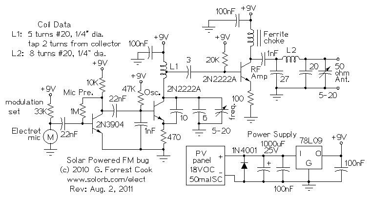
The solar power supply consists of a small 18V PV panel which charges a 1000uF electrolytic capacitor. The capacitor keeps the circuit running during brief interruptions of light, such as a bird flying over the PV panel. The 18V is regulated down to 9V with the 78L09 regulator IC to provide a steady 9V supply for the rest of the circuitry. With the PV panel shown above, the circuit will only work when direct sunlight is shining on the panel. A larger panel that can provide 22mA at 12V during cloudy conditions would extend the circuit's operating conditions.
The Electret microphone is biased with a 33K resistor, the resistor value can be changed to vary the amount of modulation and optimize the performance of specific microphones. The microphone signal is amplified by a 2N3904 audio amplifier. This signal is sent to the 2N2222A oscillator stage where it changes the oscillator's frequency (FM). The oscillator's operating frequency is set by L1, the 6pF capacitor and the 5-20pF variable capacitor. With L1 wound as specified on the schematic, the circuit will operate near the low end (88Mhz) of the FM broadcast band.
The output of the oscillator circuit is taken from a tap on the oscillator coil L1 and fed to the RF amplifier 2N2222A transistor. The output of the RF amp is run through a low pass PI filter to remove unwanted RF harmonics before the signal is sent to the antenna.
Specifications
Output Frequency: 88Mhz nominal, can cover 88-108Mhz with coil adjustments
Input voltage: 11-18VDC
Operating current: 22mA @18VDC
DC input to RF amp: 81mW
RF output power: 40mW (approx.)
Construction
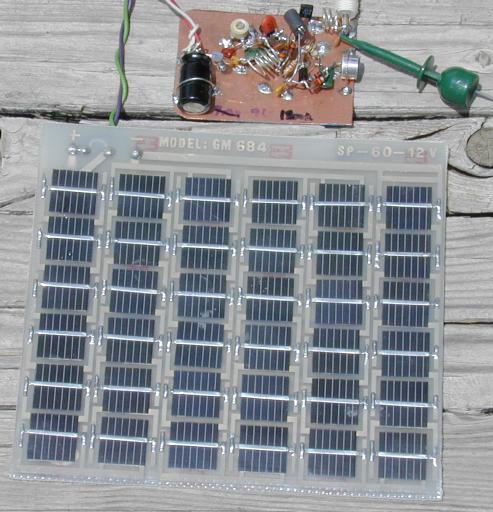
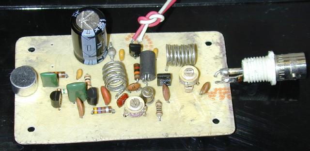
The prototype circuit shown in the top photo was built using the "dead bug" construction method, it was laid out as the circuit was designed. A second-generation version of the circuit was built using a home-made printed circuit board, this is shown in the second photo. The frequency stability of the transmitter was greatly improved when it was built with the circuit board. Artwork for the PCB is available at the end of this page.
It important to mount the oscillator components solidly so that they don't move around and cause unwanted frequency shift. The component leads for all of the RF wiring should be kept short. The coils were wound on a #2 Philips screwdriver shaft and stretched out a bit. To improve the circuit's frequency stability, wind the oscillator coil on a 1/4" form, then heat the coil in an oven at to anneal the metal. A layer of polystyrene "Q dope" can be painted onto the coil to further improve the stability.
Another trick that will improve the transmitter's frequency stability is to build it into a metal box that is surrounded by an insulating material such as styrofoam or bubble-wrap. If the transmitter box is mounted in the shade, it will be less likely to change frequency due to solar heating and cloud shading.
Antennas
This circuit will work with a variety of antennas. An adequate short-range antenna can be as simple as a 1' to 2' wire connected directly to the circuit. A resonant antenna such as a tuned dipole or a vertical antenna will greatly extend the range of the transmitter.
A resonant half-wave diple antenna for 90Mhz can be made with two 2.6 foot pieces of wire fed in the middle, using the classic dipole formula: quarter wave length (feet) = 234 / frequency (Mhz). the PV panel and wiring should be kept away from the antenna, or in the case of a short whip antenna, the PV wiring can be run in the opposite direction as the antenna to act as the other half (counterpoise) of a dipole.
Alignment
The circuit can be aligned in the laboratory by putting 12V to 18V DC across the PV panel to power the regulator. Tune your receiver to a blank spot on the lower end of the FM band and adjust the frequency calibration trimmer until you hear the microphone signal. Turn the trimmer very slowly, alignment takes a light touch. Don't turn the receiver volume up too much or you will get audio feedback. A frequency counter may be useful for setting the output frequency. It may be necessary to retune the frequency a bit after the circuit has warmed up in the sun.
The output capacitor should be tuned for the maximum transmitted signal, this setting varies with different antennas. The best way to do this is to connect the antenna to the transmitter and monitor the signal with an oscilloscope (100 Mhz bandwidth) connected to a nearby antenna. Adjust the control for the highest signal. If you have a receiver with a signal strength indicator, that can also be used for monitoring the transmitter's output level. Adjustment of the output capacitor will pull the oscillator frequency a bit, it will be necessary to alternate between oscillator and output adjustments to fully align the circuit.
Use
Place the PV panel in the sun and tune your receiver to the bug's signal, listen to the world outdoors. An analog receiver is best for picking up the signal since, unlike a digital receiver, it can be fine tuned to track the signal. I use a 1970s vintage Pioneer receiver to good effect. Once the bug's temperature has stabilized, its frequency should not drift very much.
The microphone enclosure and placement can be tuned to optimize sound reception in a particular direction. A good directional microphone can be made by putting the mic element into one end of a short piece of PVC pipe. Inserting a thin tube of porous foam into the pipe can lower the resonant nature of the cylinder.
Parts
1X GM 684 60 mA 18V PV panel (available from Electronix Express) or equivalent
1X 78L09 voltage regulator IC
1X 1N4001 diode
1X 2N3904A transistor
2X 2N2222A transistors
1X 1000uF 25V electrolytic capacitor
1X Electret microphone
4X 100nF capacitors
2X 22nF capacitor
1X 1nF capacitor
1X 3pF silver mica capacitor
1X 6pF silver mica capacitor
1X 10pF silver mica capacitor
1X 20pF ceramic disk capacitor
1X 27pF ceramic disk capacitor
2X 5-20pF (or similar) miniature variable capacitor
1X six hole ferrite choke or equivalent
1X 100 ohm 1/4W resistor
1X 470 ohm 1/4W resistor
1X 10K 1/4W resistor
1X 20K 1/4W resistor
1X 33K 1/4W resistor
1X 47K 1/4W resistor
1X 1M 1/4W resistor
1X 1-3/4"x3" copper plated blank printed circuit board
1' length of #20 tinned copper hookup wire for making two coils
1X weatherproof plastic box (recommended)
Related Links
Downloads
Solar Powered Long Range FM Transmitter - Link
|
|
|
| |
Accurate LC Meter
Build your own Accurate LC Meter (Capacitance Inductance Meter) and start making your own coils and inductors. This LC Meter allows to measure incredibly small inductances making it perfect tool for making all types of RF coils and inductors. LC Meter can measure inductances starting from 10nH - 1000nH, 1uH - 1000uH, 1mH - 100mH and capacitances from 0.1pF up to 900nF. The circuit includes an auto ranging as well as reset switch and produces very accurate and stable readings. |
|
PIC Volt Ampere Meter
Volt Ampere Meter measures voltage of 0-70V or 0-500V with 100mV resolution and current consumption 0-10A or more with 10mA resolution. The meter is a perfect addition to any power supply, battery chargers and other electronic projects where voltage and current must be monitored. The meter uses PIC16F876A microcontroller with 16x2 backlighted LCD. |
|
|
|
60MHz Frequency Meter / Counter
Frequency Meter / Counter measures frequency from 10Hz to 60MHz with 10Hz resolution. It is a very useful bench test equipment for testing and finding out the frequency of various devices with unknown frequency such as oscillators, radio receivers, transmitters, function generators, crystals, etc. |
|
1Hz - 2MHz XR2206 Function Generator
1Hz - 2MHz XR2206 Function Generator produces high quality sine, square and triangle waveforms of high-stability and accuracy. The output waveforms can be both amplitude and frequency modulated. Output of 1Hz - 2MHz XR2206 Function Generator can be connected directly to 60MHz Counter for setting precise frequency output. |
|
|
|
BA1404 HI-FI Stereo FM Transmitter
Be "On Air" with your own radio station! BA1404 HI-FI Stereo FM Transmitter broadcasts high quality stereo signal in 88MHz - 108MHz FM band. It can be connected to any type of stereo audio source such as iPod, Computer, Laptop, CD Player, Walkman, Television, Satellite Receiver, Tape Deck or other stereo system to transmit stereo sound with excellent clarity throughout your home, office, yard or camp ground. |
|
USB IO Board
USB IO Board is a tiny spectacular little development board / parallel port replacement featuring PIC18F2455/PIC18F2550 microcontroller. USB IO Board is compatible with Windows / Mac OSX / Linux computers. When attached to Windows IO board will show up as RS232 COM port. You can control 16 individual microcontroller I/O pins by sending simple serial commands. USB IO Board is self-powered by USB port and can provide up to 500mA for electronic projects. USB IO Board is breadboard compatible. |
|
|
|
|
ESR Meter / Capacitance / Inductance / Transistor Tester Kit
ESR Meter kit is an amazing multimeter that measures ESR values, capacitance (100pF - 20,000uF), inductance, resistance (0.1 Ohm - 20 MOhm), tests many different types of transistors such as NPN, PNP, FETs, MOSFETs, Thyristors, SCRs, Triacs and many types of diodes. It also analyzes transistor's characteristics such as voltage and gain. It is an irreplaceable tool for troubleshooting and repairing electronic equipment by determining performance and health of electrolytic capacitors. Unlike other ESR Meters that only measure ESR value this one measures capacitor's ESR value as well as its capacitance all at the same time. |
|
Audiophile Headphone Amplifier Kit
Audiophile headphone amplifier kit includes high quality audio grade components such as Burr Brown OPA2134 opamp, ALPS volume control potentiometer, Ti TLE2426 rail splitter, Ultra-Low ESR 220uF/25V Panasonic FM filtering capacitors, High quality WIMA input and decoupling capacitors and Vishay Dale resistors. 8-DIP machined IC socket allows to swap OPA2134 with many other dual opamp chips such as OPA2132, OPA2227, OPA2228, dual OPA132, OPA627, etc. Headphone amplifier is small enough to fit in Altoids tin box, and thanks to low power consumption may be supplied from a single 9V battery. |
|
|
|
|
|
Arduino Prototype Kit
Arduino Prototype is a spectacular development board fully compatible with Arduino Pro. It's breadboard compatible so it can be plugged into a breadboard for quick prototyping, and it has VCC & GND power pins available on both sides of PCB. It's small, power efficient, yet customizable through onboard 2 x 7 perfboard that can be used for connecting various sensors and connectors. Arduino Prototype uses all standard through-hole components for easy construction, two of which are hidden underneath IC socket. Board features 28-PIN DIP IC socket, user replaceable ATmega328 microcontroller flashed with Arduino bootloader, 16MHz crystal resonator and a reset switch. It has 14 digital input/output pins (0-13) of which 6 can be used as PWM outputs and 6 analog inputs (A0-A5). Arduino sketches are uploaded through any USB-Serial adapter connected to 6-PIN ICSP female header. Board is supplied by 2-5V voltage and may be powered by a battery such as Lithium Ion cell, two AA cells, external power supply or USB power adapter. |
|
200m 4-Channel 433MHz Wireless RF Remote Control
Having the ability to control various appliances inside or outside of your house wirelessly is a huge convenience, and can make your life much easier and fun. RF remote control provides long range of up to 200m / 650ft and can find many uses for controlling different devices, and it works even through the walls. You can control lights, fans, AC system, computer, printer, amplifier, robots, garage door, security systems, motor-driven curtains, motorized window blinds, door locks, sprinklers, motorized projection screens and anything else you can think of. |
|
|
|