| |
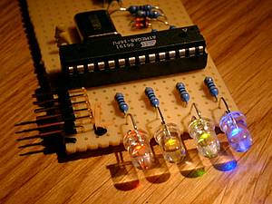
The USB-LED-Fader is a device to control a number of LEDs via USB. I built it to display the online status of my internet connection, the recording status of my video recorder (VDR), and warnings if the available disk-space is low. You can imagine an endless number of applications for this.
The LEDs are controlled with pulse width modulation (PWM). That way, they are not only on or off, it is possible to control the brightness. Included in the device are a number of 'waveforms' that can be displayed through the LEDs. That way, one LED can display some kind of a sine- or triangular wave without any interaction with the controlling host.
Every LED can be controlled individually; each one can display its own waveforms.
You can assign three different waves to every LED. The first two (0 & 1) are 'eternal' waves. They are displayed alternating until anything different is required. The third wave (2) is only displayed once; afterwards the device will switch back to alternating between the first two waves.
They are displayed alternating until anything different is required. The third wave (2) is only displayed once, afterwards the device will switch back to alternating between the first two waves.
One wave is described by three parameters: the waveform, the duration for one repetition of the wave and the number of repetitions before switching to the next wave.
This version supports four LEDs. It should be quite easy to change that number to between one and eight. I have not tested any number greater than four, but I can imagine that the load on the controller may be too high to reliably communicate via USB.
There are three parts included in the distribution: The firmware for an ATmega8 microcontroller, a command line client that can be run under Linux, and the circuits needed to build the device.
This project is based on the PowerSwitch example application by Objective Development. Like that, it uses Objective Development's firmware-only USB driver for Atmel's AVR microcontrollers.
Objective Development's USB driver is a firmware-only implementation of the USB 1.1 standard (low speed device) on cheap single chip microcomputers of Atmel's AVR series, such as the ATtiny2313 or even some of the small 8-pin devices. It implements the standard to the point where useful applications can be implemented. See the file "firmware/usbdrv/usbdrv.h" for features and limitations.
Building and installing
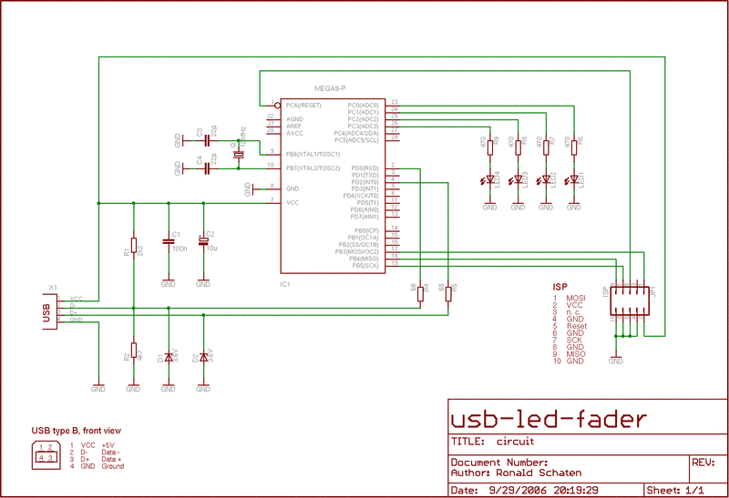
Circuit
The circuit contains only a few standard components. There's no special USB-chip involved.
The installation is described in the documentation.
Usage
Connect the device to the USB port. All LEDs should flash up to indicate that the device is initialized.
Then use the command line client as follows:
usb-led-fader status
usb-led-fader set
usb-led-fader clear
usb-led-fader reset
usb-led-fader show
usb-led-fader test
When using the set function, it is possible to define several waves at once. You simply have to give the parameters for all waves. See examples below.
Parameters
ledId: ID of the LED (0-n, depending on the number of LEDs in your circuit).
waveId: ID of the wave (0-1: constant waves, 2: override).
waveformId: ID of the waveform (0-31: brightness, 32-37: patterns). For a reference to the patterns, use the show function.
periodDuration: Time in sec/10 for one repetition of the waveform. A value of 0 can be used to reset the wave.
repetitionCount: Number of repetitions before switching to the next wave. A value of 0 can be used to repeat this forever.
Examples
Get the status of all LEDs:
usb-led-fader status
This will result in output similar to this:
LED 0 curid curvalue curpos currep nextupd
0 2 26 0 23
wave waveform length repeat duration updtime
0 38 32 1 20 45
1 0 1 1 0 1
2 0 1 1 0 1
LED 1 curid curvalue curpos currep nextupd
0 14 19 0 19
wave waveform length repeat duration updtime
0 38 32 1 20 45
1 0 1 1 0 1
2 0 1 1 0 1
LED 2 curid curvalue curpos currep nextupd
0 31 16 0 43
wave waveform length repeat duration updtime
0 38 32 1 20 45
1 0 1 1 0 1
2 0 1 1 0 1
LED 3 curid curvalue curpos currep nextupd
0 6 9 0 39
wave waveform length repeat duration updtime
0 38 32 1 20 45
1 0 1 1 0 1
2 0 1 1 0 1
In this output, the values curvalue, curpos, nextupd and updtime are for debugging purposes only. They shouldn't be of interest to the common user. The meaning of the other values should be clear.
Set the first LED to keep a moderate brightness:
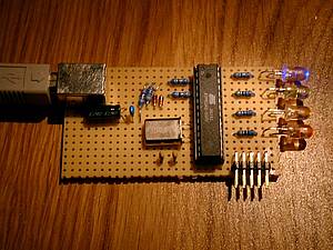
The device from above
I know that I could have soldered that in a more beautiful way... ;-)
usb-led-fader set 0 0 15 10 1
So, on LED 0 the wave 0 is set to waveform 15. It will stay there for one second and will be repeated once before switching to the next wave. There is no next wave because we didn't define one, so this waveform will stay forever.
Now set a second wave on the first LED, a little brighter than the one before:
usb-led-fader set 0 1 25 10 1
This is wave 1 on LED 0. Waveform 25 has been defined as a constant level of brightness. After setting the second wave, it will alternate with the first one after every second, because both waves have the same duration and the same number of repetitions.
Set a third wave on the first LED:
usb-led-fader set 0 2 36 20 5
This sets the third wave (wave 2) on the first LED. Waveform 36 is a nice sine-like wave, so the LED starts to fade. One period of the fading takes 2 seconds, it is repeated for 5 times. Since this is the third wave, after the repetitions the LED returns to alternating between wave 0 and wave 1, this wave is discarded.
Set multiple waves at once:
usb-led-fader set 0 0 15 10 1 0 1 25 10 1 0 2 36 20 5
This will set all of the above waves at once. Thus, the first LED will first fade the sine-wave five times, then start alternating between the two brightnesses in one-second-rhythm.
Clear the first LED:
usb-led-fader clear 0
This will clear all three waves on the first LED.
Reset the device:
usb-led-fader reset
All LEDs will flash once, to indicate that the device is reset and the LEDs are working.
Show a waveform on the screen:
usb-led-fader show 36
This will lead to an output like the following:
wave 36 - length 64
31: *****
30: *********
29: ***********
28: ***************
27: *****************
26: *******************
25: *******************
24: *********************
23: ***********************
22: *************************
21: *************************
20: ***************************
19: *****************************
18: *****************************
17: *******************************
16: *********************************
15: ***********************************
14: ***********************************
13: *************************************
12: ***************************************
11: ***************************************
10: *****************************************
9: *******************************************
8: *********************************************
7: *********************************************
6: ***********************************************
5: *************************************************
4: *****************************************************
3: *******************************************************
2: ***********************************************************
1: ****************************************************************
================================================================
Keep in mind that the width of the displayed wave corresponds to the length of the waveform. If you display a very simple one like the constant brightness levels (0-31), the length is 1. Therefore only one column is displayed.
Test the device:
usb-led-fader test
This function sends many random numbers to the device. The device returns the packages, and the client looks for differences in the sent and the received numbers.
Drawbacks
As mentioned above, controlling the PWM for several LEDs is a lot of work for one small microcontroller. So is speaking the USB protocol. Together, these result in a lot of load on the device, so the communication with the device is not 100% reliable. More than 99%, though, at least in our tests.
|
|
|
| |
Accurate LC Meter
Build your own Accurate LC Meter (Capacitance Inductance Meter) and start making your own coils and inductors. This LC Meter allows to measure incredibly small inductances making it perfect tool for making all types of RF coils and inductors. LC Meter can measure inductances starting from 10nH - 1000nH, 1uH - 1000uH, 1mH - 100mH and capacitances from 0.1pF up to 900nF. The circuit includes an auto ranging as well as reset switch and produces very accurate and stable readings. |
|
PIC Volt Ampere Meter
Volt Ampere Meter measures voltage of 0-70V or 0-500V with 100mV resolution and current consumption 0-10A or more with 10mA resolution. The meter is a perfect addition to any power supply, battery chargers and other electronic projects where voltage and current must be monitored. The meter uses PIC16F876A microcontroller with 16x2 backlighted LCD. |
|
|
|
60MHz Frequency Meter / Counter
Frequency Meter / Counter measures frequency from 10Hz to 60MHz with 10Hz resolution. It is a very useful bench test equipment for testing and finding out the frequency of various devices with unknown frequency such as oscillators, radio receivers, transmitters, function generators, crystals, etc. |
|
1Hz - 2MHz XR2206 Function Generator
1Hz - 2MHz XR2206 Function Generator produces high quality sine, square and triangle waveforms of high-stability and accuracy. The output waveforms can be both amplitude and frequency modulated. Output of 1Hz - 2MHz XR2206 Function Generator can be connected directly to 60MHz Counter for setting precise frequency output. |
|
|
|
BA1404 HI-FI Stereo FM Transmitter
Be "On Air" with your own radio station! BA1404 HI-FI Stereo FM Transmitter broadcasts high quality stereo signal in 88MHz - 108MHz FM band. It can be connected to any type of stereo audio source such as iPod, Computer, Laptop, CD Player, Walkman, Television, Satellite Receiver, Tape Deck or other stereo system to transmit stereo sound with excellent clarity throughout your home, office, yard or camp ground. |
|
USB IO Board
USB IO Board is a tiny spectacular little development board / parallel port replacement featuring PIC18F2455/PIC18F2550 microcontroller. USB IO Board is compatible with Windows / Mac OSX / Linux computers. When attached to Windows IO board will show up as RS232 COM port. You can control 16 individual microcontroller I/O pins by sending simple serial commands. USB IO Board is self-powered by USB port and can provide up to 500mA for electronic projects. USB IO Board is breadboard compatible. |
|
|
|
|
ESR Meter / Capacitance / Inductance / Transistor Tester Kit
ESR Meter kit is an amazing multimeter that measures ESR values, capacitance (100pF - 20,000uF), inductance, resistance (0.1 Ohm - 20 MOhm), tests many different types of transistors such as NPN, PNP, FETs, MOSFETs, Thyristors, SCRs, Triacs and many types of diodes. It also analyzes transistor's characteristics such as voltage and gain. It is an irreplaceable tool for troubleshooting and repairing electronic equipment by determining performance and health of electrolytic capacitors. Unlike other ESR Meters that only measure ESR value this one measures capacitor's ESR value as well as its capacitance all at the same time. |
|
Audiophile Headphone Amplifier Kit
Audiophile headphone amplifier kit includes high quality audio grade components such as Burr Brown OPA2134 opamp, ALPS volume control potentiometer, Ti TLE2426 rail splitter, Ultra-Low ESR 220uF/25V Panasonic FM filtering capacitors, High quality WIMA input and decoupling capacitors and Vishay Dale resistors. 8-DIP machined IC socket allows to swap OPA2134 with many other dual opamp chips such as OPA2132, OPA2227, OPA2228, dual OPA132, OPA627, etc. Headphone amplifier is small enough to fit in Altoids tin box, and thanks to low power consumption may be supplied from a single 9V battery. |
|
|
|
|
|
Arduino Prototype Kit
Arduino Prototype is a spectacular development board fully compatible with Arduino Pro. It's breadboard compatible so it can be plugged into a breadboard for quick prototyping, and it has VCC & GND power pins available on both sides of PCB. It's small, power efficient, yet customizable through onboard 2 x 7 perfboard that can be used for connecting various sensors and connectors. Arduino Prototype uses all standard through-hole components for easy construction, two of which are hidden underneath IC socket. Board features 28-PIN DIP IC socket, user replaceable ATmega328 microcontroller flashed with Arduino bootloader, 16MHz crystal resonator and a reset switch. It has 14 digital input/output pins (0-13) of which 6 can be used as PWM outputs and 6 analog inputs (A0-A5). Arduino sketches are uploaded through any USB-Serial adapter connected to 6-PIN ICSP female header. Board is supplied by 2-5V voltage and may be powered by a battery such as Lithium Ion cell, two AA cells, external power supply or USB power adapter. |
|
200m 4-Channel 433MHz Wireless RF Remote Control
Having the ability to control various appliances inside or outside of your house wirelessly is a huge convenience, and can make your life much easier and fun. RF remote control provides long range of up to 200m / 650ft and can find many uses for controlling different devices, and it works even through the walls. You can control lights, fans, AC system, computer, printer, amplifier, robots, garage door, security systems, motor-driven curtains, motorized window blinds, door locks, sprinklers, motorized projection screens and anything else you can think of. |
|
|
|