| Part's
List:
|
|
2x 47K
1x 10K
1x 82K
1x 50K POT
|
|
|
1x 33uF
1x 10uF
3x 100nF (104)
1x 100pF (101)
1x 10pF (10)
|
|
1x NJM2035 IC
1x 38 KHz Crystal |
|
|
|
| Technical
Specifications:
|
Voltage Supply: 1.2V - 3.6V MAX
Current Draw: >3mA
Channel Separation: < 25dB
Signal to Noise Ratio: 67 dB
Operation Temperature: -20 - 75°C
Frequency Range: 20Hz - 15KHz |
|
|
|
HI-FI
Stereo Encoder / Multiplexer
| |
This stereo encoder
is the perfect solution for those looking for a high
quality stereo sound transmission at a low cost. This
stereo encoder produces an excellent crystal clear stereo
sound and very good channel separation that can match
with many more expensive stereo encoders that are available
on the market. It is all possible thanks to a 38KHz
quartz crystal that controls the 19kHz pilot tone, so
you will never have to calibrate or re-adjust the circuit.
NJM2035 offers superb quality and is manufactured by
NJR CORPORATION (JRC), a subsidiary of New Japan Radio,
a company that is known as the world’s best manufacturer
of high end professional audio semiconductors. This
transmitter will work with any mono FM transmitter including
TX300 and TX500 which are available on our website.
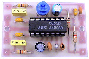
The whole circuit may easily fit on a small 1”
x 1.5” printed circuit board allowing to fit in
places where space is limited. While building your stereo
encoder please take your time and always double check
with the schematic to make sure that all the connections
are done correctly. If you have any questions, comments
or suggestion we will be glad to further assist you.
|
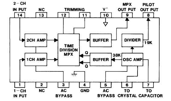
NJM2035
- Internal Block
Diagram
How
Does Stereo Encoder Work?
| |
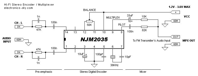
The stereo encoder consists of three main stages; pre-emphasis,
digital encoder and mixer stages.
Pre-emphasis stage is achieved by using two 47K
resistors and two 1nF capacitors. This helps to
eliminate the noise that is produced during the
FM transmission of your audio signal.
Second stage that is built around NJM2035 is a digital
encoder. All of its internal blocks except for two
audio amplifiers (pins 1 & 14) that act as separators
are created using digital circuits. The first digital
circuit is a 38KHz oscillator that is generated
by using external 38KHz crystal (pin 7), 10pF capacitor
(pin 6) and 100pF bypass capacitor (pin 5). Once
38KHz frequency is generated it is then buffered
and divided into two 19KHz signals with a phase
difference of 180 degrees. Once that is done these
two frequencies are connected with two time division
MPX digital alternating switchers ,one for each
audio channel. Here audio channels are switched
between each other with a total frequency of 38KHz.
If you would be able to slow this frequency to 1Hz
per second you would be able to hear that this all
but a trick. During the first half of the second
you would hear the left audio channel and during
the second half of the second you would hear the
right audio channel. Due to the fact that the channels
are switched with a fast frequency of 38KHz per
second our brain is unable to recognize that these
channels are really switched and receives this as
a continuous audio signal. At the same time another
signal from the 38KHz oscillator is divided by half
into 19KHz. This signal is called a PILOT tone because
it will help a stereo decoder on the receiver’s
part to slice the MULTIPLEX signal (mixed L and
R audio channels) and separate them back into left
and right audio channels.
The third stage is a mixer that consists of 33uF
and 100nF capacitors and 82K and 10K resistors.
The role of this circuit is to mix the multiplex
subcarrier and pilot signals together. The multiplex
subcarrier signal that is coming out from the pin
9 of the NJM2035 IC is the sum and difference of
both left and right audio channels that are switched
at 38Khz rate. The PILOT signal that is coming out
of pin 8 is a 19KHz frequency that is used to distinguish
what channel is currently being switched and without
which stereo decoding would not be possible.
|
How
to Connect a Stereo Encoder to your FM Transmitter
| |
1) First test your FM Transmitter and make sure that an audio signal
is properly transmitted on your desired frequency. Once that is done turn off your
transmitter and disconnect its audio inputs.
2) Connect left and right audio outputs from your audio source to the inputs of your
stereo encoder.
3) Connect stereo encoder’s MPX output to your transmitter’s input (audio
coax cable highly recommended).
4) Turn on your transmitter, FM receiver and audio source (making sure its audio volume
is not too loud), and apply voltage supply from a single 1.5 battery cell to a stereo
encoder.
5) By now you should hear a stereo sound. Adjust 50K potentiometer making sure your
L-R balance is set to the middle and adjust the volume of your audio source making
sure an audio signal is as clear as possible.
|
Frequently
Asked Questions
| |
1. Can I replace
NJM2035 with BA1404?
No. BA1404 chip has been manufactured by a different
company and these two chips have different internal
architecture and pin connections.
2. Can I use my own pre-emphasis circuit?
Yes that’s feasible. All you have to do
is short circuit 47K resistor / 1nF capacitor
and connect your pre-emphasis to audio inputs.
3. Stereo Encoder works but the transmitted
music comes out distorted. What can I do to
eliminate that distortion?
You have to remember not to over-modulate NJM2035
inputs with higher / louder audio signals than
it can handle. Placing 10K stereo potentiometer
on audio inputs can help eliminate that problem,
although it is not necessary to achieve a good
sound quality. All you have to do is lower the
volume of the incoming audio source.
4. Stereo Encoder works but the transmitted
music comes out with noise. What can be done
to eliminate that noise?
Stereo Encoder has to be grounded properly and
cannot be too close to the transmitter’s
oscillator as it might cause an oscillation.
Another reason might be a lack of proper filtering
on your power supply, if you are using one.
If that’s the case make sure that all
the diodes on the rectifier are bypassed with
a 10n capacitors and that your voltage supply
is well filtered with at least 4700uF capacitor.
5. Can I supply the encoder with a single 1.5V
battery cell.
Yes. In fact due to the very little power consumption
(>3mA) of the NJM2035 chip your encoder should
work for quite a while when supplying from just
one single 1.5V battery!
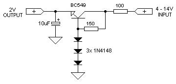
6. I want to connect the encoder to the supply
voltage of my FM transmitter which is higher
than 1.5 V, how can this be done?
You can easily build a simple power converter
for the stereo encoder with a few simple components
as shown below.
7. Can I use my transmitter's existing pre-emphasis?
Pre-emphasis can only be used before stereo
encoder’s Audio Inputs not after its MPX
Output. Doing otherwise may produce undesired
results as MPX signal contains crucial 19KHz
PILOT signal needed for stereo decoding.
8. If I will use a stereo encoder will any mono
FM receiver be able to receive the audio signal?
Yes. MPX stream that is generated by NJM2035
contains both stereo and mono audio signals.
9. Is it true that stereo transmitters
require stronger power output comparing to mono
FM transmitters?
Stereo transmitters may require 'slightly' stronger
power output to achieve clear stereo sound on
the receiving part because transmitter has to
also carry out clear 19KHz PILOT signal without
which stereo transmission is not possible. If
stereo FM receiver does not receive a clear
PILOT tone it may change from stereo to mono
reception.
|
Where
to get components or purchase Stereo Encoder Kit
| |
If you are building the
above Stereo Encoder and have trouble finding
some of the components like NJM2035 or 38KHz
crystals, we are distributing the following
components in our Electronics-DIY store and also the kit version
in Electronic
Kits section.
|
Related Links
|
|
|
| |
Accurate LC Meter
Build your own Accurate LC Meter (Capacitance Inductance Meter) and start making your own coils and inductors. This LC Meter allows to measure incredibly small inductances making it perfect tool for making all types of RF coils and inductors. LC Meter can measure inductances starting from 10nH - 1000nH, 1uH - 1000uH, 1mH - 100mH and capacitances from 0.1pF up to 900nF. The circuit includes an auto ranging as well as reset switch and produces very accurate and stable readings. |
|
PIC Volt Ampere Meter
Volt Ampere Meter measures voltage of 0-70V or 0-500V with 100mV resolution and current consumption 0-10A or more with 10mA resolution. The meter is a perfect addition to any power supply, battery chargers and other electronic projects where voltage and current must be monitored. The meter uses PIC16F876A microcontroller with 16x2 backlighted LCD. |
|
|
|
60MHz Frequency Meter / Counter
Frequency Meter / Counter measures frequency from 10Hz to 60MHz with 10Hz resolution. It is a very useful bench test equipment for testing and finding out the frequency of various devices with unknown frequency such as oscillators, radio receivers, transmitters, function generators, crystals, etc. |
|
1Hz - 2MHz XR2206 Function Generator
1Hz - 2MHz XR2206 Function Generator produces high quality sine, square and triangle waveforms of high-stability and accuracy. The output waveforms can be both amplitude and frequency modulated. Output of 1Hz - 2MHz XR2206 Function Generator can be connected directly to 60MHz Counter for setting precise frequency output. |
|
|
|
BA1404 HI-FI Stereo FM Transmitter
Be "On Air" with your own radio station! BA1404 HI-FI Stereo FM Transmitter broadcasts high quality stereo signal in 88MHz - 108MHz FM band. It can be connected to any type of stereo audio source such as iPod, Computer, Laptop, CD Player, Walkman, Television, Satellite Receiver, Tape Deck or other stereo system to transmit stereo sound with excellent clarity throughout your home, office, yard or camp ground. |
|
USB IO Board
USB IO Board is a tiny spectacular little development board / parallel port replacement featuring PIC18F2455/PIC18F2550 microcontroller. USB IO Board is compatible with Windows / Mac OSX / Linux computers. When attached to Windows IO board will show up as RS232 COM port. You can control 16 individual microcontroller I/O pins by sending simple serial commands. USB IO Board is self-powered by USB port and can provide up to 500mA for electronic projects. USB IO Board is breadboard compatible. |
|
|
|
|
ESR Meter / Capacitance / Inductance / Transistor Tester Kit
ESR Meter kit is an amazing multimeter that measures ESR values, capacitance (100pF - 20,000uF), inductance, resistance (0.1 Ohm - 20 MOhm), tests many different types of transistors such as NPN, PNP, FETs, MOSFETs, Thyristors, SCRs, Triacs and many types of diodes. It also analyzes transistor's characteristics such as voltage and gain. It is an irreplaceable tool for troubleshooting and repairing electronic equipment by determining performance and health of electrolytic capacitors. Unlike other ESR Meters that only measure ESR value this one measures capacitor's ESR value as well as its capacitance all at the same time. |
|
Audiophile Headphone Amplifier Kit
Audiophile headphone amplifier kit includes high quality audio grade components such as Burr Brown OPA2134 opamp, ALPS volume control potentiometer, Ti TLE2426 rail splitter, Ultra-Low ESR 220uF/25V Panasonic FM filtering capacitors, High quality WIMA input and decoupling capacitors and Vishay Dale resistors. 8-DIP machined IC socket allows to swap OPA2134 with many other dual opamp chips such as OPA2132, OPA2227, OPA2228, dual OPA132, OPA627, etc. Headphone amplifier is small enough to fit in Altoids tin box, and thanks to low power consumption may be supplied from a single 9V battery. |
|
|
|
|
|
Arduino Prototype Kit
Arduino Prototype is a spectacular development board fully compatible with Arduino Pro. It's breadboard compatible so it can be plugged into a breadboard for quick prototyping, and it has VCC & GND power pins available on both sides of PCB. It's small, power efficient, yet customizable through onboard 2 x 7 perfboard that can be used for connecting various sensors and connectors. Arduino Prototype uses all standard through-hole components for easy construction, two of which are hidden underneath IC socket. Board features 28-PIN DIP IC socket, user replaceable ATmega328 microcontroller flashed with Arduino bootloader, 16MHz crystal resonator and a reset switch. It has 14 digital input/output pins (0-13) of which 6 can be used as PWM outputs and 6 analog inputs (A0-A5). Arduino sketches are uploaded through any USB-Serial adapter connected to 6-PIN ICSP female header. Board is supplied by 2-5V voltage and may be powered by a battery such as Lithium Ion cell, two AA cells, external power supply or USB power adapter. |
|
200m 4-Channel 433MHz Wireless RF Remote Control
Having the ability to control various appliances inside or outside of your house wirelessly is a huge convenience, and can make your life much easier and fun. RF remote control provides long range of up to 200m / 650ft and can find many uses for controlling different devices, and it works even through the walls. You can control lights, fans, AC system, computer, printer, amplifier, robots, garage door, security systems, motor-driven curtains, motorized window blinds, door locks, sprinklers, motorized projection screens and anything else you can think of. |
|
|
|