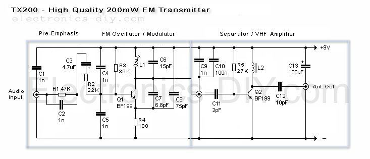
About TX200 - 200mW FM Transmitter
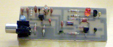
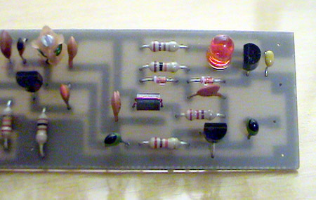
TX200 uses only two coils; one in the oscillator and the other one in the 200mW VHF amplifier so it should be fairly easy for anyone to build. It also includes built-in pre-emphasis and C5 for enhanced sound quality. While assembling the transmitter care must be taken to make sure that C1 is directly connected to L1 and C9 to L2. These caps eliminate the distortions form the DC supply and improve the sound quality greatly. 9V voltage supply is also very important because it provides the exact amount of current to Q1 to produce loud and clear sound quality. I hope that you'll have as much fun as I had while building this transmitter.
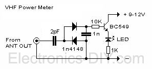
Power Meter
TX200 comes with built-in LED based power meter. This is a very helpful tool that will tell you if your transmitter's oscillator is working properly. If RF signal is transmitted the LED will illuminate. Besides that, it will also give you a quick visual way to check how much power is being transmitted. I highly recommend that you have the transmitter and power meter on the same PCB. If you like to experiment a lot, you will appreciate this inexpensive but externally helpful addition.
How to use PLL to digitally tune the frequency of the TX200 transmitter
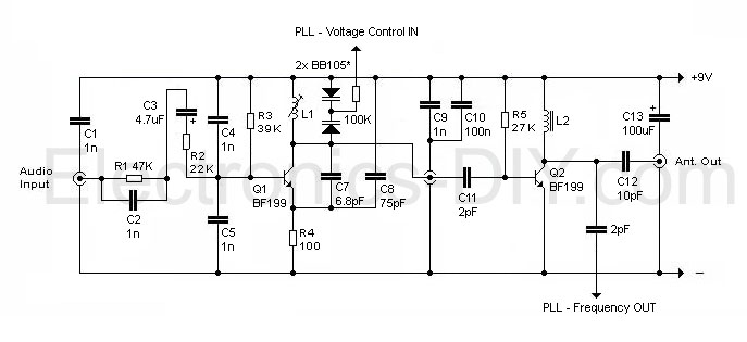
If you want to use Phase Locked Loop (PLL) to digitally tune the frequency of TX200 then you will need to make small changes to the transmitter's oscillator. Theoretically, change original variable frequency oscillator (VFO) to voltage controlled oscillator (VCO). PLL uses voltage to change the capacitance of the varicap diodes / frequency of the oscillator so two BB105 varicap diodes or any 15-30pF varicaps will be perfect for this.
You vary the capacitance of the varicap diode(s) by applying voltage supply between 1 - 8V. If you apply 1V the capacitance will be around 34pF, and if you apply 8-30V the capacitance will be 12pF (minimum). Now, you may wonder why do we need to start from 1V? The reason is that if you apply voltages below 1V the capacitance may go as high as 200pF and we simply can't use that. 100K resistor will be used to lower the current of the voltage, because varicaps require only 0.2mA of current to operate!
With this knowledge we replace C6 - 15pF capacitor with two varicaps and one resistor. That much is enough to be able to use 1 - 8V voltage to change the oscillator's frequency. The second change that we will need to make is to use 2pF capacitor and connect it to the Q2 transistor's collector. PLL will use this to sample the frequency and compare it with digitally selected frequency. PLL will then compare those frequencies and if they are not the same PLL with vary the voltage that is applied to the varicaps, until those two frequencies are the same.
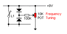
Before you even connect PLL circuit to the TX200 transmitter you will need to test if the oscillator is working properly. We can tune through entire FM band (88-108MHz) by applying the voltage to the varicaps. To do so, connect "PLL - Voltage Control" PIN to the 10K potentiometer as shown below. With this setup you will be able to use potentiometer to change the frequency of the transmitter. If you can't go through the entire FM band or if your frequency is out completely then you will need to change the inductance of the L1 coil.
PLL Module
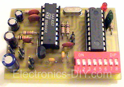
The schematic and instructions for building this PLL module can be found at pira.cz. After building it and doing some testing with it I was amazed by how well this Phase Locked Loop circuit performs. It's stable, compact, very easy to build and connecting it to TX200 transmitter was a piece of cake!
Make TX200 a Stereo Transmitter
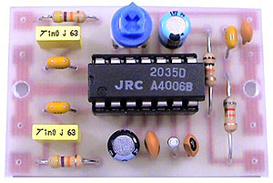
You can easily turn TX200 into a high quality stereo transmitter by connecting this stereo encoder module that you can either
build it yourself or
buy it as a kit. Stereo encoder kit includes all the hard to find components such as NJM2035 IC and 38KHz crystal.
Parts List
R1 - 47K
R2 - 22K
R3 - 39K
R4 - 100
R5 - 27K
C1, C2, C4, C5, C9 - 1n
C3 - 4.7uF
C6 - 15pF
C7 - 6.8pF
C8 - 75pF
C10 - 100nF
C11 - 2pF
C12 - 10pF
C13 - 100uF
Q1, Q2 - BF199
L1 - 3.5 turns / 5mm dia. variable coil (65nH - 80nH).
L2 - Ferrite bead 1 turn or use 1uH inductor.
Technical Specifications
Supply Voltage: 9V
Power Consumption: 35mA
RF Power: 200mW
Where to get the Parts
If you are building the above FM Transmitter and have trouble finding components such as variable coils, BF199 transistors or ferrite beads we are distributing these components in our
Electronics-DIY store.