| |
The ESR Meter is basically an AC Ohmmeter with special scales and protective circuitry. It provides a continuous reading of series resistance in electrolytic capacitors. It operates at 100 kHz to keep the capacitive reactance factor near zero. The remaining series resistance is due to the electrolyte between the capacitor plates and indicates the state of dryness. Capacitor termination problems also show up plainly due to the continuous ohmic reading. The ESR meter uses 8 operational amplifiers. An op-amp is an idealized basic amplifier with two inputs. The non-inverting input (+) has an in-phase relationship with the op-amp output, and the inverting input (-) an out-of-phase relationship. Op-amps are usually used with negative feedback and reach a stable operating condition when their two inputs are equal in voltage.
Op-amps IA & 1B form a regenerative 100 kHz oscillator circuit. Capacitor C1 is the basic timing capacitor and RI is selected to set frequency. Diodes D2 & D3 clip the bottom and top of the output waveform so that the output level and frequency are resistant to battery voltage changes.

ESR METER INSTRUCTIONS
Check every electrolytic you see. Your judgement of ESR increases with experience. You'll notice that capacitors usually check very good or very bad. Marginal capacitors accelerate their own failure.
Variable ESR when wiggling leads: Capacitor is unreliable. Replace. (Be sure test clips are tight and direct to capacitor leads; don't use chassis ground.)
Over 50 Ohms: It should be replaced. Even if it works today, it will probably fail within a year. You're doing the customer a favor by replacing it now and may be saving yourself a recall.
50-20 Ohms: OK for 1 to 50 MFD in medium or high impedance
circuits like signal coupling or timing circuits.
For capacitors over 50 MFD, we have established a general limit which is based on manufacturer's data, circuit theory, and experience:
C X R = 1000
(MFD) (OHMS) (MAXIMUM)
Examples: 100 MFD : 10 Ohms Max.
1000 MFD : 1 Ohm Max.
10,000 MFD : 0.1 Ohm Max.
Capacitors smaller than 1.0 MFD can be checked by comparison with an out-of-circuit capacitor of equal type & capacitance. This will show approximate capacitance, opens, shorts (usually zero ohms), and intermittent terminations, Tt1s always been a problem trying to attach a copper or steel lead to aluminum foil~
With marginal capacitors, try paralleling or substituting with a known good one and re-check equipment performance. Circuit requirements for ESR vary somewhat.
The ESR Meter can monitor ESR in live circuits up to 600 volts, provided the circuit ripple doesn't change the reading from what you had with the circuit off. The ESR Meter will ignore about 10 volts p-p at 120 Hz; less at higher frequencies.
We don't recommend testing live circuits because of the shock hazard and because we haven't found it necessary.
Change batteries when the Zero Adjust setting changes drastically. Battery changing instructions are inside the ESR Meter.
Keep solvents and sprays away from the plastic meter cover.
ADDITIONAL INSTRUCTIONS
1. A shorted electrolytic will check good on the ESR Meter, but is rare. Less than 1% of all field-failures are shorted.
2. Non-Polarized electrolytics check the same as Polarized.
3. Directly parallel led electrolytics must be separated for ESR testing.
4. Your one year warranty excludes breakage & batteries.
CIRCUIT DESCRIPTION
The ESR meter uses 8 operational ainplifiers. An op-amp is an idealized basic amplifier with two inputs. The non-inverting input (+) has an in-phase relationship with the op-amp output, and the inverting input (-) an out-of-phase relationship. Op-amps are usually used with negative feedback and reach a stable operating condition when their two inputs are equal in voltage.
Op-amps IA & 1B form a regenerative 100 kHz oscillatnr circuit. Capacitor C1 is the basic tiining capacitor and RI is selected to set frequency. Diodes D2 & D3 clip the bottom and top of the output waveform so that the output level and frequency are resistant to battery voltage changes.
The oscillator output of op-amp 1B drives 10-ohm source resistor R8F. The test-capacitor, thru the test leads, couples this 100 kllz signal to 10-ohm load resistor R9F. The amount of voltage developed here is indicative of the capacitors ESR value. (The 10-ohm resistors determine the basic iieter scaling.)
Capacitor C3 blocks any DC voltage present on the test-capacitor. Diodes D4 & D5 protect the ESR Meter from any initial charging current to C3. Resistor R7 discharges C3 after test.
A DC operating bias of 0.55 V is established by diode D1 for the oscillator stage and for all subsequent stages, which are DCcoupled and operated class A. DC bias from D1 and ESR signal from R9F are combined at the input of op-amp 1D. Both voltages are amplified by 1D, 1C, & 2A. Each of these three stages has an amplification factor of about 2.8 due to the ratio of output-voltage to feedback~voltage at the (-) input, which is determined -by feedback resistors R13F & R14F, etc.
Op-amp 2D is configured as a peak-to-peak detector. when the in-corning AC signal goes more positive than the normal bias level of about 0.77 Volt, the output of 2D also goes positive. But it must go positive enough to overcome the voltage drop across diode D6 before a fully equalizing positive voltage can be fed back to the -(-) input thru R20 to stabilize the op-amp.
-Capacitor C4 is charged to the peak value of the AC signal and accurately represents the peak of the incoming AC signal. The voltage drop across the diode becomes almost inconsequential due to the feedback process, and the circuit works down to a few mV.
A similar action occurs during the negative peak, using D7 & C5.
Resistor R21 provides a constant minimum amount of negative feed--back around op-amp 2D. The negative feedback increases the op-amp bandwidth which, most importantly, keeps the amplifier input-to-output phase-shift low enough for proper circuit operation.
The two outputs from the peak-to-peak detector are connected to two high-input-impedance unity-gain DC amplifiers, which drive the 1 mA meter movement differentially.
FAILURE MODES
Our ESR Meter has proven to be a very reliable instrument in field use. The very few failures that have occurred were simple electrical or mechanical problems. Component failures have been ZERO. In one unit, a resistor lead appeared to take solder but didn't. In another unit, battery electrolyte leaked onto the PCB. After THOROUGHLY cleaning the PCB, the unit worked fine. Two units were intermittent due to loose meter-terminal nuts. If intermittency appears, make sure these nuts are TIGHT and the PCB nuts SNUG. If the PCB nuts are tighter than the meter-terminal nuts, the meter nuts "float" on the screw threads and produce a poor connection to the PCB. Problems? Our expert 1-day service is usually free.
1. ICI & 1C2 are National LM324N or equivalent.
2. "F" resistors are 1% tolerance; all others 5%
3. R7 must be 0.5 W; all others 0.5 W or less.
4. IC1 selected for 100 kHz oscillation capability.
5. R1 sets frequency: 1K to 3.3K ohms.
6. R10 optional, selected improves scale linearity.
7. R15 optional; assists IC output pul1-down in some units.
8. R21 sets linearity at mid-scale: 330 to 2.2K~ ohms.
9. R24 optional; corrects DC offset at infinity ESR.
10. R26 helps set zero (full-scale): 68 to 240 ohms.
11. D6 & D7 selected for correct reading at 50 ohms ESR.
12. Calibrate at 75F. Wait 20 minutes after soldering PCB.
Values some have had trouble reading:
R6F=150 ohms
R12F=681 ohms
Checks capacitors from 1 to 10,000 MFD in-circuit.
Shows up intermittent opens. Measures dryness of the electrolyte.
Our research on field failures of electrolytics reveals that almost all of them fail because of high ESR (equivalent series resistance). The high internal resistance reduces the capacitor's rate of charge and discharge, effectively making it an "open" capacitor.
High ESR usually results from dehydration of the electrolyte due to equipment heat, old age, poor sealing, or internal heat from ESR and high ripple currents (why input filters fail most).
Another common reason for high ESR is defective terminations due to broken welds, loose crimps or rivets, and/or corrosion. These problems cause variable ESR or intermittent opens and can usually be detected by monitoring ESR while wiggling the capacitor leads.
We have yet to find an electrolytic capacitor with normal ESR whose circuit failure was due to capacitance change alone. This helps to explain why traditional capacitance meters have never been popular with the service industry. THE REAL PROBLEM WITH ELECTROLYTICS ISN'T CAPACITANCE CHANGE, IT'S ESR CHANGE!
Only about 1% of todays electrolytic failures are leaky or shorted. Both types cause obvious circuit voltage changes or burned parts
The other 99% can be located instantly with the ESR Meter!
The ESR meter can be used in-circuit because circuit resistances are large compared to normal ESR values. By testing at only 25 mV rms , semiconductor circuit components are not activated. Test lead polarity is unnecessary because the test voltage is AC (50KHZ).
Discharging not necessary! A small internal capacitor couples ESR but blocks DC up to 6OOV. Can frequently be used on live circuits.
Note: ESR, being electrochemical in nature, is influenced by temperature. By testing in the 65-850F range (room temperature), corrections for temperature are unnecessary, especially since you're looking for ESR changes of 10 to 100 times above normal.
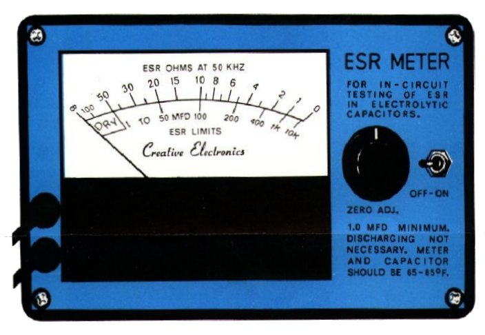
The meter's upper scale shows the capacitor's present ESR condition -and the lower scale shows you the ESR working limit for that size capacitor in MFD. Capacitors over SO ohms are dry and unreliable.
Most of the time you don't even need to know the capacitor s value because the reading is obvious, usually very high or very low. The DC voltage rating doesn't matter because ESR is independent of it.
Safely tests the electrolytics with the power off. Avoids current surges that temporarily "heal" the bad connection in electrolytics. No mQre ',blown" semiconductors from paralleling live capacitors.
Related Links
Downloads
ESR Meter - Link
|
|
|
| |
Accurate LC Meter
Build your own Accurate LC Meter (Capacitance Inductance Meter) and start making your own coils and inductors. This LC Meter allows to measure incredibly small inductances making it perfect tool for making all types of RF coils and inductors. LC Meter can measure inductances starting from 10nH - 1000nH, 1uH - 1000uH, 1mH - 100mH and capacitances from 0.1pF up to 900nF. The circuit includes an auto ranging as well as reset switch and produces very accurate and stable readings. |
|
PIC Volt Ampere Meter
Volt Ampere Meter measures voltage of 0-70V or 0-500V with 100mV resolution and current consumption 0-10A or more with 10mA resolution. The meter is a perfect addition to any power supply, battery chargers and other electronic projects where voltage and current must be monitored. The meter uses PIC16F876A microcontroller with 16x2 backlighted LCD. |
|
|
|
60MHz Frequency Meter / Counter
Frequency Meter / Counter measures frequency from 10Hz to 60MHz with 10Hz resolution. It is a very useful bench test equipment for testing and finding out the frequency of various devices with unknown frequency such as oscillators, radio receivers, transmitters, function generators, crystals, etc. |
|
1Hz - 2MHz XR2206 Function Generator
1Hz - 2MHz XR2206 Function Generator produces high quality sine, square and triangle waveforms of high-stability and accuracy. The output waveforms can be both amplitude and frequency modulated. Output of 1Hz - 2MHz XR2206 Function Generator can be connected directly to 60MHz Counter for setting precise frequency output. |
|
|
|
BA1404 HI-FI Stereo FM Transmitter
Be "On Air" with your own radio station! BA1404 HI-FI Stereo FM Transmitter broadcasts high quality stereo signal in 88MHz - 108MHz FM band. It can be connected to any type of stereo audio source such as iPod, Computer, Laptop, CD Player, Walkman, Television, Satellite Receiver, Tape Deck or other stereo system to transmit stereo sound with excellent clarity throughout your home, office, yard or camp ground. |
|
USB IO Board
USB IO Board is a tiny spectacular little development board / parallel port replacement featuring PIC18F2455/PIC18F2550 microcontroller. USB IO Board is compatible with Windows / Mac OSX / Linux computers. When attached to Windows IO board will show up as RS232 COM port. You can control 16 individual microcontroller I/O pins by sending simple serial commands. USB IO Board is self-powered by USB port and can provide up to 500mA for electronic projects. USB IO Board is breadboard compatible. |
|
|
|
|
ESR Meter / Capacitance / Inductance / Transistor Tester Kit
ESR Meter kit is an amazing multimeter that measures ESR values, capacitance (100pF - 20,000uF), inductance, resistance (0.1 Ohm - 20 MOhm), tests many different types of transistors such as NPN, PNP, FETs, MOSFETs, Thyristors, SCRs, Triacs and many types of diodes. It also analyzes transistor's characteristics such as voltage and gain. It is an irreplaceable tool for troubleshooting and repairing electronic equipment by determining performance and health of electrolytic capacitors. Unlike other ESR Meters that only measure ESR value this one measures capacitor's ESR value as well as its capacitance all at the same time. |
|
Audiophile Headphone Amplifier Kit
Audiophile headphone amplifier kit includes high quality audio grade components such as Burr Brown OPA2134 opamp, ALPS volume control potentiometer, Ti TLE2426 rail splitter, Ultra-Low ESR 220uF/25V Panasonic FM filtering capacitors, High quality WIMA input and decoupling capacitors and Vishay Dale resistors. 8-DIP machined IC socket allows to swap OPA2134 with many other dual opamp chips such as OPA2132, OPA2227, OPA2228, dual OPA132, OPA627, etc. Headphone amplifier is small enough to fit in Altoids tin box, and thanks to low power consumption may be supplied from a single 9V battery. |
|
|
|
|
|
Arduino Prototype Kit
Arduino Prototype is a spectacular development board fully compatible with Arduino Pro. It's breadboard compatible so it can be plugged into a breadboard for quick prototyping, and it has VCC & GND power pins available on both sides of PCB. It's small, power efficient, yet customizable through onboard 2 x 7 perfboard that can be used for connecting various sensors and connectors. Arduino Prototype uses all standard through-hole components for easy construction, two of which are hidden underneath IC socket. Board features 28-PIN DIP IC socket, user replaceable ATmega328 microcontroller flashed with Arduino bootloader, 16MHz crystal resonator and a reset switch. It has 14 digital input/output pins (0-13) of which 6 can be used as PWM outputs and 6 analog inputs (A0-A5). Arduino sketches are uploaded through any USB-Serial adapter connected to 6-PIN ICSP female header. Board is supplied by 2-5V voltage and may be powered by a battery such as Lithium Ion cell, two AA cells, external power supply or USB power adapter. |
|
200m 4-Channel 433MHz Wireless RF Remote Control
Having the ability to control various appliances inside or outside of your house wirelessly is a huge convenience, and can make your life much easier and fun. RF remote control provides long range of up to 200m / 650ft and can find many uses for controlling different devices, and it works even through the walls. You can control lights, fans, AC system, computer, printer, amplifier, robots, garage door, security systems, motor-driven curtains, motorized window blinds, door locks, sprinklers, motorized projection screens and anything else you can think of. |
|
|
|


