| |
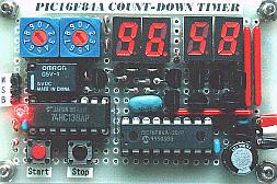
60 Minute Count Down Timer |
|
Here is a 60 minute countdown timer that can be used as an exposure timer for UV light boxes, photography, egg timer, and many other projects where counting or delay is necessary. The heart of the countdown timer is PIC16F84A chip and 4 digit character LED display. The relay is energized after the count down timer goes down from specified minute and second until zero.
Processing explanation
of Count-down timer
Title
;********************************************************
;
; The Count-down timer processing
;
; Author : Seiichi Inoue
;********************************************************
I wrote the title of the program using the comment( ; ).
LIST and INCLUDE directive
list p=pic16f84a
include p16f84a.inc
Processor type is set by LIST directive.
The standard label definition of PIC16F84A is read by the INCLUDE directive.
As for the change of the standard label definition of PIC16F84A, refer to "Processing explanation of signboard".
Or you can use ERRORLEVEL directive to suppress the Warning messages.
Configuration Word
Configuration Word is specified using CONFIG directive.
__config _hs_osc & _wdt_off & _pwrte_on & _cp_off
Configuration Word can be set when writing a program by the programmer. However, it is automatically established when using CONFIG directive.
As for the contents of operand, refer to "Processing explanation of signboard".
Item Contents Field name Bit(s)
Code Protection OFF CP 1111111111
Power-up Timer ON PWRTE(inv) 0
Watchdog Timer OFF WDTE 0
Oscillator Selection HS FOSC1 and FOSC0 10
Label definition
;**************** Label Definition ********************
The definition of the label constant to use by the processing is done. The standard label of PIC16F84A is read in INCLUDE directive.
The pattern definition of the 7 segment LED is specified by the EQU, too.
A pattern is shown below.
'0' : Lighting-up, '1' : Going-out.
TOP VIEW
a b c d e f g
0 0 0 0 0 0 0 1
1 1 0 0 1 1 1 1
2 0 0 1 0 0 1 0
3 0 0 0 0 1 1 0
4 1 0 0 1 1 0 0
5 0 1 0 0 1 0 0
6 0 1 0 0 0 0 0
7 0 0 0 1 1 1 1
8 0 0 0 0 0 0 0
9 0 0 0 0 1 0 0
Debug mode specification
;************** Debugging mode setting ****************
;For debugging mode, ";" of next line should be removed.
;#define _debug
It sometimes had better modify the part of the processing step when debugging software.
This time, the initial value of the counter value, the set value of the timer, the condition of the stop switch are set for the debugging. However, this time, I was made to be able to change the part to assemble by the definition of the '_debug' label.
For the details, refer to "Debugging of Count-down timer".
Program start
;**************** Program Start ***********************
Instruction is executed from Zero addresses of the program memory when making the power ON of the PIC. When there is interruption processing, processing is begun from the addresse 4.
It makes each processing jump with the GOTO instruction.
Initialization process
;**************** Initial Process *********************
The following processings are done as the initialization processing after the turning on.
It sets a mode at port A.
It sets four of port A from the 0th to the 3rd to the output port and it sets the 4th to the input port.
It uses the 4th port for the input port of the STOP key.
It sets B port pull-up function(RPBU=0).
As for the pull-up function, refer to "The specification of B port ( RB0-RB3 )".
It sets the condition of the timer start-up.
It uses an internal clock. The prescaler is used for TMR0. The prescaler value is 256.
It sets the output of the 3rd port at port A to '1'.
It sets a relay to the OFF condition.
It writes the lighting-up pattern of 7 segments in the RAM memory.
It sets 0 to the second counter.
It sets a non-time-out condition to the time-out display memory (the flag).
Timer stand-by process
;************* Timer stand-by Process *****************
In the condition that the count-down of the timer hasn't started, the following processing is repeatedly executed.
It sets the set value of the BCD switch to the count value.
It outputs the contents of the counter to the LED.
It sets the 6th port of port B to the input mode.
It checks the condition of the start switch.
Timer start process
;************** Timer start Process *******************
The following processing is executed when detecting that the start switch became ON with the timer stand-by process.
It makes a relay ON.
It executes the initialization of the interruption timer.
It is necessary to make have interruption in 1 second as correctly as possible.
To decide the interruption time of the timer, there is a following element.
The oscillator frequency : I use 10-MHz oscillation.
The set value of prescaler. : I set to 256.
I set a maximum to make the interruption number of times little.
The count value of the hard timer : I set for an error to be minimized. ( 213 counts )
The set value is 256-213=43.
The set value of the soft counter : It sets for an error to be minimized. ( 46 counts )
It sets an interruption possible condition.
Processing since then is repeatedly executed until there is a time-out.
It outputs the contents of the counter to the LED.
The checking of a time-out condition
At the time of the time-out, it returns to the initialization processing.
The interruption time can be calculated by the following formula.
The interruption time = (4/OSC freq) x Prescaler x Hard timer count x Soft count
= 0.4 x 10-6 x 256 x 217 x 45
= 0.999936 seconds
Above-mentioned value is a value with few errors and little interruption time.
When using 4.19 MHz as the oscillator, the precision at the time of the hard timer count value=186, the soft timer count value=22 was the best and was to be in 1.000049642 seconds.
The actual circuit doesn't become as the calculation in the frequency precision of the oscillator and the relation of the soft processing after interruption. It is necessary to adjust after making.
The error when count-downed in 99 minutes with the equipment which I made was to be in -20 seconds(The timer is faster).
It becomes 0.003367 seconds when converting to the error in 1 second. Therefore, I did to the hard timer count value=213, the soft timer count value=46. The interruption time in this case is as follows. After adjusting a value, it became an error in 1 second within 99 minutes.
The interruption time = (4/OSC freq) x Prescaler x Hard timer count x Soft count
= 0.4 x 10-6 x 256 x 213 x 46
= 1.0033152 seconds
The set value of hard timer (TMR0) becomes the value which subtracted the count value to want for from 256.
256-213=43(2Bh)
LED control subroutine
;************** LED Control Subroutine ****************
The contents of the counter are output to the LED in order of the 10th of the minute, the 1st of the minute, the 10th of the second, the 1st of the second.
Change from the binary-coded decimal code(BCD) into the 7 segment data
;******* Change BCD to 7segment data Subroutine *******
It changes from the data of the binary-coded decimal code into the data in 7 segments and outputs to port B.
Timer subroutine of 1 millisecond
;************* 1msec Timer Subroutine *****************
Port B is controlling the BCD switches, the start switch, the LEDs. It is necessary to do time a little for the transistor to become ON even if it specifies each device. This transition time is very short(Several-µ second). However, when a 10-MHz clock is used, the PIC operating time of 1 step is a 0.4-µ second. When there are few numbers of the steps in PIC, the time of the decoder control is shorter than transition time of the transistor. So, it is executing the wait processing of 1 millisecond after specifying devices such as the BCD switch. To be 1 millisecond isn't necessary. I think that there is not a problem even if it is short a little. This depends on the characteristic of the transistor. Display's flickering occurs when the waiting time is long.
When using at the input mode like the BCD switchs, the start switch, it executes a 1-millisecond wait before reading the condition of the device after specifying a device. When using at the output mode like the 7 segment LEDs, it executes the processing of the following device after waiting 1 millisecond after presenting the lighting-up information of the LED.
It is difficult to know a necessity in the waiting time by the simulation of MLPAB. I understood it by the operation of the actual circuit. It is necessary to consider in the operating time of the hardware, too.
This subroutine is diverting the processing which was made in "LED flasher".
Interruption process
;************ Begin Interruption Process **************
It does the saving of W register and the saving of STATUS register and it confirms a timer interrupt.
The point which should be careful here is in the bank condition. When the interruption occurs immediately after changing a bank to 1 in interruped processing, it sets SFR which was mistaken by the interruption processing. So, it is executed in the processing which changes a bank to 0 after the saving of STATUS register is ended.
Interruption ending process
;************ END of Interruption Process **************
It returns STATUS register and W register and it ends the interruption processing with the interruption ending instruction (RETFIE). With this, it becomes the interruption possible condition.
SWAPF instruction is used for the processing to return W register so as not for the contents of the STATUS register to change.
Time-out interruption process
;*********** Time-out interruption Process ************
This processing is executed when the timer TMR0 of the hardware does in the time-out.
To have count-down processing every second, it is short only at the hardware timer. (A maximum of 26 milliseconds in case of the 10-MHz clock)
So, it counts the interruption of the hard timer by the software and it is making execute count-down processing every second.
I decide the set value of the hard timer and the count value of the software to minimize the error of the count-down.
Count-down process
;************* Timer count-down Process ***************
Processing is executed every second.
It is checking first, do subtract the 1st counter in the second and whether or not it becomes 0. In case of 0, because there is possibility of the time-out situation, it is doing the checking whether or not all counters are 0. To judge 0 of the counter, it reads counter content by the movf instruction and it is checking the Z bit of the STATUS register. The Z bit is '1' means the contents of the counter are 0.
When either counter is not 0, because it is not in the time-out condition, count-down processing is executed.
In the count-down processing, it checks the contents of each counter and in case of 0, a maximum is set. The maximum of the 10th of the second is 5 and as for the other digit, 9 is a maximum. When the contents of the counter are not 0, it subtracts one.
In the interruption processing, only time-out checking and count-down processing are executed. The time-out processing(Timer stop and Relay OFF) and the LED display processing are executed by the timer start processing.
End of coding
;********************************************************
; END of signboard control processing
;********************************************************
end
At the end of coding, END directive is used.
|
|
|
| |
Accurate LC Meter
Build your own Accurate LC Meter (Capacitance Inductance Meter) and start making your own coils and inductors. This LC Meter allows to measure incredibly small inductances making it perfect tool for making all types of RF coils and inductors. LC Meter can measure inductances starting from 10nH - 1000nH, 1uH - 1000uH, 1mH - 100mH and capacitances from 0.1pF up to 900nF. The circuit includes an auto ranging as well as reset switch and produces very accurate and stable readings. |
|
PIC Volt Ampere Meter
Volt Ampere Meter measures voltage of 0-70V or 0-500V with 100mV resolution and current consumption 0-10A or more with 10mA resolution. The meter is a perfect addition to any power supply, battery chargers and other electronic projects where voltage and current must be monitored. The meter uses PIC16F876A microcontroller with 16x2 backlighted LCD. |
|
|
|
60MHz Frequency Meter / Counter
Frequency Meter / Counter measures frequency from 10Hz to 60MHz with 10Hz resolution. It is a very useful bench test equipment for testing and finding out the frequency of various devices with unknown frequency such as oscillators, radio receivers, transmitters, function generators, crystals, etc. |
|
1Hz - 2MHz XR2206 Function Generator
1Hz - 2MHz XR2206 Function Generator produces high quality sine, square and triangle waveforms of high-stability and accuracy. The output waveforms can be both amplitude and frequency modulated. Output of 1Hz - 2MHz XR2206 Function Generator can be connected directly to 60MHz Counter for setting precise frequency output. |
|
|
|
BA1404 HI-FI Stereo FM Transmitter
Be "On Air" with your own radio station! BA1404 HI-FI Stereo FM Transmitter broadcasts high quality stereo signal in 88MHz - 108MHz FM band. It can be connected to any type of stereo audio source such as iPod, Computer, Laptop, CD Player, Walkman, Television, Satellite Receiver, Tape Deck or other stereo system to transmit stereo sound with excellent clarity throughout your home, office, yard or camp ground. |
|
USB IO Board
USB IO Board is a tiny spectacular little development board / parallel port replacement featuring PIC18F2455/PIC18F2550 microcontroller. USB IO Board is compatible with Windows / Mac OSX / Linux computers. When attached to Windows IO board will show up as RS232 COM port. You can control 16 individual microcontroller I/O pins by sending simple serial commands. USB IO Board is self-powered by USB port and can provide up to 500mA for electronic projects. USB IO Board is breadboard compatible. |
|
|
|
|
ESR Meter / Capacitance / Inductance / Transistor Tester Kit
ESR Meter kit is an amazing multimeter that measures ESR values, capacitance (100pF - 20,000uF), inductance, resistance (0.1 Ohm - 20 MOhm), tests many different types of transistors such as NPN, PNP, FETs, MOSFETs, Thyristors, SCRs, Triacs and many types of diodes. It also analyzes transistor's characteristics such as voltage and gain. It is an irreplaceable tool for troubleshooting and repairing electronic equipment by determining performance and health of electrolytic capacitors. Unlike other ESR Meters that only measure ESR value this one measures capacitor's ESR value as well as its capacitance all at the same time. |
|
Audiophile Headphone Amplifier Kit
Audiophile headphone amplifier kit includes high quality audio grade components such as Burr Brown OPA2134 opamp, ALPS volume control potentiometer, Ti TLE2426 rail splitter, Ultra-Low ESR 220uF/25V Panasonic FM filtering capacitors, High quality WIMA input and decoupling capacitors and Vishay Dale resistors. 8-DIP machined IC socket allows to swap OPA2134 with many other dual opamp chips such as OPA2132, OPA2227, OPA2228, dual OPA132, OPA627, etc. Headphone amplifier is small enough to fit in Altoids tin box, and thanks to low power consumption may be supplied from a single 9V battery. |
|
|
|
|
|
Arduino Prototype Kit
Arduino Prototype is a spectacular development board fully compatible with Arduino Pro. It's breadboard compatible so it can be plugged into a breadboard for quick prototyping, and it has VCC & GND power pins available on both sides of PCB. It's small, power efficient, yet customizable through onboard 2 x 7 perfboard that can be used for connecting various sensors and connectors. Arduino Prototype uses all standard through-hole components for easy construction, two of which are hidden underneath IC socket. Board features 28-PIN DIP IC socket, user replaceable ATmega328 microcontroller flashed with Arduino bootloader, 16MHz crystal resonator and a reset switch. It has 14 digital input/output pins (0-13) of which 6 can be used as PWM outputs and 6 analog inputs (A0-A5). Arduino sketches are uploaded through any USB-Serial adapter connected to 6-PIN ICSP female header. Board is supplied by 2-5V voltage and may be powered by a battery such as Lithium Ion cell, two AA cells, external power supply or USB power adapter. |
|
200m 4-Channel 433MHz Wireless RF Remote Control
Having the ability to control various appliances inside or outside of your house wirelessly is a huge convenience, and can make your life much easier and fun. RF remote control provides long range of up to 200m / 650ft and can find many uses for controlling different devices, and it works even through the walls. You can control lights, fans, AC system, computer, printer, amplifier, robots, garage door, security systems, motor-driven curtains, motorized window blinds, door locks, sprinklers, motorized projection screens and anything else you can think of. |
|
|
|