| |
3W FM Transmitter Amplifier |
|
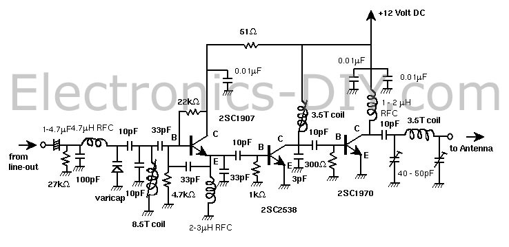
Presented is a three stage 3W FM Transmitter Amplifier using 2SC9018, 2SC2053 and 2SC1970 transistors. The circuit is supplied by 12-14V DC voltage and requires at least 500mA of current.
Component List of FM Transmitter
Registors:
1 27K 1/4 -1/8 Watt === (red-violet-orange)
1 4.7K 1/4 -1/8 Watt === (yellow-violet-red)
1 22K 1/4 Watt === (red-red-orange)
1 51 1/4 Watt === (green-brown-black)
1 1K 1/4 Watt === (brown-black-red)
1 300 1/4 Watt === (orange-black-brown)
Capacitors:
1 100PF (101) Ceramic
4 10PF Ceramic
3 33PF Ceramic
1 3-4PF Ceramic
2 0.01MF (103) Ceramic
1 1-4.7 MF Electrolytic
Trimmer Capacitor (optional)
When you make coils by yourself-->Diagram
2 40-50PF
1 10-20PF
Coils:
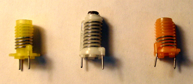
1 8.5 Turns Molded Coil (5mm diameter bobbin)(inductance=ca.0.6-0.7MH)
2 3.5-4.5 Turns Molded Coil (5mm diameter bobbin)(inductance=ca.0.3MH)
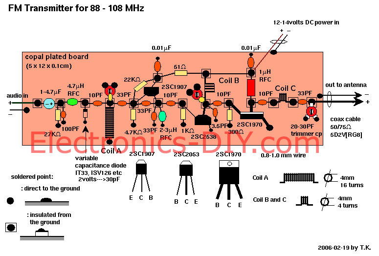
You could make them by yourself. Prepare a 5.0 mm diameter cylinderical material and enameled/polyurethane wire of 0.8-1.0 mm diameter.
The movie shows how to do. Please note that for this work, you must have a frequency counter by all means.
Inductors:
1 1MH Fixed RFC
1 2.2MH Fixed RFC
1 4.7MH Fixed RFC
Semiconductors:
1 2SC1907 Transistor
1 2SC2538 or 2053 Transistor
1 2SC1970 Transistor
1 Variable Capacitor (Vari-cap)[ex. ISV126, IT33 or MV209]
Two sided Copper Plate:
1 5 x 10 cm minimum
15 5 X 5 mm
In case you can't obtain this material, you can use "porous circuit board". But it is a compromise, though.
Optional:
Coax Cable RG-62-u or RG-213[5D2V] -->See "How to make a simple antenna?"
Stabilizer for 12 vols (semiconductor) and the necessary capacitor (1000MF Electrolytic/25volts)
-->See "How to supply the power" and the Diagram.
FAQ for FM Transmitter
1. Some of unfamiliar parts
Q: Do the coils have an air or ferrite core?
A: Ferrite core. If you want to use air coil, you must use a bit thcker wire like 1.0 mm and protect them from trembling that leads unstable frequency. Therefore I recommend module-type coil. Different from the "simplest" model, unstable conditions of every section can cause problem of transmission and interference.
Q: Can I make the choke RFC by myself?
A: Yes it is possible. Prepare 4.7K ohm register (1/8 - 1/4 watt) and 0.2-0.5 mm coated wire. Give the wire 20-25 turns around the register. Solder the wires and the leads of the register. It will become 1-3 uH RFC. A: Higher frequency characteristics will be preferable.
Q: What type of varicap diode is required?
A: "varicap diode" is called as "variable capacitance diode", "voltage controlled diode", or "tuning diode" too. I used "1SV101" the capacity is 10-25 pF by the voltage change. There are quite a lot of replacements (MV209, MMVL3102) and the exterior is different.
Q: When I build the final stage, is the 1 microH choke above the 1970 meant to be of a bigger type than the small resistor-like ones that I'm using in the rest of the circuit?
A: the 1970 needs much ampere than the 2538 or 1907, so that it must be bigger.
2. Transistor and Porarity
Q: Can you make sure of the position for the transistors to be soldered.
A: That's all:
2sc1970 E - to earth plate
C - to 1 micro Henry RFC
B - to 10pF cap. and 300 ohm res.
2SC2538 E - to earth plate
C - to 10pF,3.5pF and coil
B - to 1K Ohm res.
2SC1907 E - to 33pF, 33pF, 10pF, 2-3 micro H. RFC
B - to 33pF, 33pF, 22K Ohm, 4.7K Ohm res.
C - to 0.01 micro F cap.
3. Tuning and Testing
Q: How can I start transmitting?
A:
(1) Don't supply the power (12 volts DC) before connecting the appropriate antenna (even if it is a simple coax cable antenna that I made instantly).
(2) You must decide the frequency you want to transmit. Please check a vacant frequency in your FM dial of your radio receiver. And prepare a power meter and a frequency counter. Although it is not so easy to build a frequency counter by yourself, it would be easier to build a power meter. The diagram is here.
(3) Before connecting the antenna to the final output (where 100pF is connected), you must adjust the final 3.5 coil. The second and final coil must be adjusted to maximize the strength of the power meter.
Q: What is the function of the 3.5 turn coil above the 2053? It does not seem to have much effect on the quality of the sound on my receiver when I move the core.
A: This is for adjusting the matching with the original signal. The reason may be that the matching is not correct or the coil is not appropriate.
4. Problems:heated transistor, noise
Q: When I tested the completed circuit, the 2SC2053 gets very hot after a minute or two. I assume this might damage it if I let it get too hot. Do I need to adjust the loading on the 2053, so it passes less current? Do you have any ideas how I may get the best output - i.e. where to connect aerial and if any parts need adding or changing?
A: When you have too hot temperature at 2SC2538 (when the adjustment of the final coil is complete, it will not become hot, anyway), you may exchange 50 ohm (I suggested to change before) at 2SC1907's C for 100 ohm. This means to reduce the power voltage to the first section.
Q: Can I use an "AC adopter" for 12 volts?
A: You can, but sometimes it may cause hum nose. So get a 12 volt power supply of over 1A (1000 mA) direct current with good quality. When you use not so sophisticated "AC adapter", please add the 12 volt power regulater to the initial schimatic.
5. Antenna
Q: What type of antenna will I need?
A: I suggest that first you buy a ready made FM antenna for 88-108MHz (not for TV).
I think you can get it at Radio Shack or equivalent. Please tell them "I want to receive week airwaves of FM radio", then they will show you some model. Every receiving antenna can be used for transmitting as well.
When you buy it, please get the cable to connect antenna with transmitter. Sometimes the cable is appendant to antenna. But the cable must be quite a thick 50 or 75 Ohm coaxial cable (type of "5D2V", "5C2V","RG62", etc.). You will fix this antenna on the top of your roof and will pull the cable into your radio room.
6. Starting up
Q: Let me know how to start the transmission up?
A: Prepare the following materials:
1. Tape recorder with mini plug cable coming from audio out.
2. 12v/over 500mA DC power supply or 12v car battery.
3. Radio antenna with enough wire to reach antenna from place of transmission.
To build the system:
1. Connect the antenna and the transmitter using the coaxial cable connector. Make sure the connection is right; if you use it without doing so, the power transistor may get damage.
2. Connect the audio cable from the headphone jack or line out to the audio in on the Black box (check that the volume is down on the tape player).
3. Everything OK? If so, connect the 12v power to the transmitter (never mix up plus and minus!).
4. Start your tape player, tune your radio to the transmitting frequency (89.1MHz) and you will find the signal. Bring up the volume little by little until you've reached the appropriate level. Now you are an independent narrowcaster.
7. How to decrease the output power?
Q: Is it possible to have much simpler and smaller powered transmitter?
A: Look at the "most simplest transmitter" page.
Q: I'm going to do a sound installation. I want to use several very low power transmitters. Is it possible to built your transmitters with lower power? I only need a radius from one to five meter.
A: My answer would be the same above. Please note that this tiny transmitter has lower quality of sounds and unstable frequency. Every cable of audio input and battery influences the output frequecy---this can be a bit solved by using thin coaxial cables for these suply. But this s an advantage that you need not special materials such as s variable capacitance diode. In stead of that, this can cover at least 10 meter radius. This should be good for your artistic installation.
8.How to increase the output power?
Q: How to increase the output power?
A: This main unit is so sophisticatedly designed that you can boost the power only when you add a boosting circuit to it.
Related Links
Downloads
3W FM Transmitter Amplifier - Link
|
|
|
| |
Accurate LC Meter
Build your own Accurate LC Meter (Capacitance Inductance Meter) and start making your own coils and inductors. This LC Meter allows to measure incredibly small inductances making it perfect tool for making all types of RF coils and inductors. LC Meter can measure inductances starting from 10nH - 1000nH, 1uH - 1000uH, 1mH - 100mH and capacitances from 0.1pF up to 900nF. The circuit includes an auto ranging as well as reset switch and produces very accurate and stable readings. |
|
PIC Volt Ampere Meter
Volt Ampere Meter measures voltage of 0-70V or 0-500V with 100mV resolution and current consumption 0-10A or more with 10mA resolution. The meter is a perfect addition to any power supply, battery chargers and other electronic projects where voltage and current must be monitored. The meter uses PIC16F876A microcontroller with 16x2 backlighted LCD. |
|
|
|
60MHz Frequency Meter / Counter
Frequency Meter / Counter measures frequency from 10Hz to 60MHz with 10Hz resolution. It is a very useful bench test equipment for testing and finding out the frequency of various devices with unknown frequency such as oscillators, radio receivers, transmitters, function generators, crystals, etc. |
|
1Hz - 2MHz XR2206 Function Generator
1Hz - 2MHz XR2206 Function Generator produces high quality sine, square and triangle waveforms of high-stability and accuracy. The output waveforms can be both amplitude and frequency modulated. Output of 1Hz - 2MHz XR2206 Function Generator can be connected directly to 60MHz Counter for setting precise frequency output. |
|
|
|
BA1404 HI-FI Stereo FM Transmitter
Be "On Air" with your own radio station! BA1404 HI-FI Stereo FM Transmitter broadcasts high quality stereo signal in 88MHz - 108MHz FM band. It can be connected to any type of stereo audio source such as iPod, Computer, Laptop, CD Player, Walkman, Television, Satellite Receiver, Tape Deck or other stereo system to transmit stereo sound with excellent clarity throughout your home, office, yard or camp ground. |
|
USB IO Board
USB IO Board is a tiny spectacular little development board / parallel port replacement featuring PIC18F2455/PIC18F2550 microcontroller. USB IO Board is compatible with Windows / Mac OSX / Linux computers. When attached to Windows IO board will show up as RS232 COM port. You can control 16 individual microcontroller I/O pins by sending simple serial commands. USB IO Board is self-powered by USB port and can provide up to 500mA for electronic projects. USB IO Board is breadboard compatible. |
|
|
|
|
ESR Meter / Capacitance / Inductance / Transistor Tester Kit
ESR Meter kit is an amazing multimeter that measures ESR values, capacitance (100pF - 20,000uF), inductance, resistance (0.1 Ohm - 20 MOhm), tests many different types of transistors such as NPN, PNP, FETs, MOSFETs, Thyristors, SCRs, Triacs and many types of diodes. It also analyzes transistor's characteristics such as voltage and gain. It is an irreplaceable tool for troubleshooting and repairing electronic equipment by determining performance and health of electrolytic capacitors. Unlike other ESR Meters that only measure ESR value this one measures capacitor's ESR value as well as its capacitance all at the same time. |
|
Audiophile Headphone Amplifier Kit
Audiophile headphone amplifier kit includes high quality audio grade components such as Burr Brown OPA2134 opamp, ALPS volume control potentiometer, Ti TLE2426 rail splitter, Ultra-Low ESR 220uF/25V Panasonic FM filtering capacitors, High quality WIMA input and decoupling capacitors and Vishay Dale resistors. 8-DIP machined IC socket allows to swap OPA2134 with many other dual opamp chips such as OPA2132, OPA2227, OPA2228, dual OPA132, OPA627, etc. Headphone amplifier is small enough to fit in Altoids tin box, and thanks to low power consumption may be supplied from a single 9V battery. |
|
|
|
|
|
Arduino Prototype Kit
Arduino Prototype is a spectacular development board fully compatible with Arduino Pro. It's breadboard compatible so it can be plugged into a breadboard for quick prototyping, and it has VCC & GND power pins available on both sides of PCB. It's small, power efficient, yet customizable through onboard 2 x 7 perfboard that can be used for connecting various sensors and connectors. Arduino Prototype uses all standard through-hole components for easy construction, two of which are hidden underneath IC socket. Board features 28-PIN DIP IC socket, user replaceable ATmega328 microcontroller flashed with Arduino bootloader, 16MHz crystal resonator and a reset switch. It has 14 digital input/output pins (0-13) of which 6 can be used as PWM outputs and 6 analog inputs (A0-A5). Arduino sketches are uploaded through any USB-Serial adapter connected to 6-PIN ICSP female header. Board is supplied by 2-5V voltage and may be powered by a battery such as Lithium Ion cell, two AA cells, external power supply or USB power adapter. |
|
200m 4-Channel 433MHz Wireless RF Remote Control
Having the ability to control various appliances inside or outside of your house wirelessly is a huge convenience, and can make your life much easier and fun. RF remote control provides long range of up to 200m / 650ft and can find many uses for controlling different devices, and it works even through the walls. You can control lights, fans, AC system, computer, printer, amplifier, robots, garage door, security systems, motor-driven curtains, motorized window blinds, door locks, sprinklers, motorized projection screens and anything else you can think of. |
|
|
|


