| |
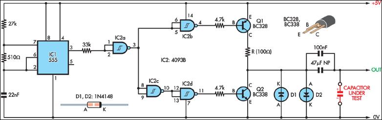
When teamed up with an oscilloscope, this simple circuit provides a means of measuring capacitor ESR.
A 555 timer (IC1) configured as a 2.3kHz free-running oscillator acts as the timebase. It provides narrow (7.7µs) pulses to the capacitor under test via a NAND Schmitt trigger (IC2) and transistor Q1.
A 100Ω resistor in series with Q1 limits current flow to about 50mA. Therefore, an ESR of 1Ω will produce pulses across the test capacitor of 50mV, which means that an oscilloscope with a vertical sensitivity of 5mV can measure ESR down to 0.1Ω or less.
Transistor Q2 discharges the test capacitor during the "off" portion of the test cycle, ensuring a zero average DC component. Diodes D1 and D2 limit the maximum output voltage to approximately 0.6V, corresponding to an ESR of 12Ω, which is adequate for most uses.
If accuracy is not critical, then the circuit could be powered from four AA batteries rather than from a regulated 5V supply.
TESTING ESR OF ELECTROLYTIC CAPACITORS
I recently found an easy and cheap way to test ESR (Equivalent Series Resistance) of electrolytic capacitors, in circuit, that might save some people a lot of time. It requires only an oscillosope and a simple signal generator.
I had an oscilloscope that I was trying to repair (Intensity control had little effect. Horiz sweep was only halfway across screen at higher freqs. One power supply rail was too low and others were too high.) and I had already checked every electrolytic capacitor in several/many different ways (all in-circuit), and even compared each of the readings to those from an identical unit: Powered off: Looked at signature from component tester (single-curve tracer) across each cap, and from each end of cap to ground, did resistance check with DMM, did capacitance check with DMM, checked resistance from each end of cap to ground. Powered on: Put scope across each cap, and scope from each end of cap to ground, used DMM and measured DC and AC voltages across each cap and from each end of cap to ground. I did find some bad caps (and some other bad components) and replaced them. But the problems were still there!
I had been wanting to order an ESR meter, but hadn't done it yet, and needed to get this scope repaired immediately. I went to Sam Goldwasser's excellent repair-FAQ site, at http://www.repairfaq.org/ and found a GREAT method for testing ESR of capacitors in-circuit that requires only a signal generator and an oscilloscope (and some cables), and had found and fixed the problem within about ten minutes!! Here's what I did (This technique is basically directly from Sam's repair faq site):
I used a signal generator and an oscilloscope to set up what I now call an "ESR Scope": At the output of the generator, I connected a BNC "tee" adapter. I ran one 50 Ohm BNC cable from the tee to a good (Tek 2465A) scope (with a 50-ohm BNC terminator on the scope input). On the other side of the tee, I connected another BNC cable that had alligator clips on its other end (It might have been a 75 ohm cable; shouldn't matter too much?), which I clipped onto the banana plugs of a set of cheap DMM-type probes.
(Terminator note: I used a Tektronix 50 Ohm "pass-through" terminator, on the scope end of the BNC cable. But, you should also be able to use, instead, another BNC "tee" on the scope input, with an "endcap" terminator on one side and the cable coming in on the other side of the tee. A standard 10BaseT Ethernet 50 Ohm coax terminator (and 50 Ohm Ethernet BNC coax cables) should work fine. And they're available at Radio Shack, and probably Staples, et al.)
I set up the signal generator to produce square waves at about 100 kHz, with about 100 mv peak-to-peak amplitude as seen on the attached scope, and no DC offset (A simple 555 timer circuit would do the job, too!). Then, I turned the scope's v/div to 5 mv/div, with time/div at 1 microsec, with AC coupling of the input.
Shorting the probes together gave me a display on the scope that was about one division high. It was basically a square wave, with large narrow peaks at each leading edge. But I only looked at the horizontal part's p-p amplitude.
That's the whole setup! No resistors. No nothing. Just cables (and a terminator). I did also try it with a decade resistor box in series with the probes, just to see what it would look like. I could clearly see each one-ohm increase, on the scope display, with the probes shorted together as well as with the probes across a good electrolytic capacitor.
When I applied the probes across a GOOD capacitor in-circuit, there was little, if any, change in the scope display, compared to when the probes were shorted (since, depending on the frequency, a capacitor should look more-or-less like a short circuit, to AC). But, when I tried it across a BAD capacitor, usually the display would be almost-totally off the screen. And, there were some caps that looked marginal, making the display go from about one div p-p up to about 3 to 5 divs (which probably corresponded with somewhere between 5 ohms and 20 ohms of ESR, if I recall correctly.)
Anyway, within just a few minutes I had found one more bad electrolytic filter cap in the power supply, two smaller bad electrolytics in the P.S., a bad one on the horizontal sweep switch's board, four bad ones near the middle of the main board, and a couple more that I can't remember right now.
I made a note of each one. When I was all done checking, the first thing I did was replace the filter cap in the power supply, and then power it on and check the power supply rails' voltages. BINGO!!!!! YESSS!!! They were all normal again! Not only that, but the horizontal sweep problem and the Intensity control problem were both GONE!! Yippee!
That filter cap had checked out as perfectly OK, using every one of the other methods that I described above (all were "in-circuit", though), and compared OK to the other identical scope's same cap, in all of those cases. But with this "ESR Scope" method, it was totally obvious, immediately. And the same cap on the other scope tested good, with this method (So, the earlier comparisons WERE bad cap vs. good cap, but showed nothing!). [I also noted that after the bad cap was removed, it tested bad in the same way that it had while it was in-circuit, with a basically identical scope display. And all of the other ones that I replaced also tested bad, when OUT of the circuit, even with the other methods.]
This " ESR Scope " method isn't a perfect panacea, of course: There were some cases where, without an identical unit to compare to, the displays would have been difficult for me to interpet, and possibly misleading. (However, it *always* worked with every *electrolytic* that I tried it on, IIRC, from 10 uF 10v to at least 1000 uF 100v, with no need for an identical unit to compare to.) But, then again, I haven't played around with it enough, yet, either. I assume that adjusting the frequency for different capacitances might be helpful, especially if non-electrolytics were to be tested. I also seem to remember that a DC offset in the signal is usually used, when testing ESR. I'll try that, later. And maybe increasing the amplitude of the square wave would be useful, sometimes, too. But, usually, I think I'll want it to be low-amplitude, probably less than +/- 0.4v, so the signal doesn't turn on any semiconductor junctions.
Related Links
Downloads
Oscilloscope ESR Tester - Link
|
|
|
| |
Accurate LC Meter
Build your own Accurate LC Meter (Capacitance Inductance Meter) and start making your own coils and inductors. This LC Meter allows to measure incredibly small inductances making it perfect tool for making all types of RF coils and inductors. LC Meter can measure inductances starting from 10nH - 1000nH, 1uH - 1000uH, 1mH - 100mH and capacitances from 0.1pF up to 900nF. The circuit includes an auto ranging as well as reset switch and produces very accurate and stable readings. |
|
PIC Volt Ampere Meter
Volt Ampere Meter measures voltage of 0-70V or 0-500V with 100mV resolution and current consumption 0-10A or more with 10mA resolution. The meter is a perfect addition to any power supply, battery chargers and other electronic projects where voltage and current must be monitored. The meter uses PIC16F876A microcontroller with 16x2 backlighted LCD. |
|
|
|
60MHz Frequency Meter / Counter
Frequency Meter / Counter measures frequency from 10Hz to 60MHz with 10Hz resolution. It is a very useful bench test equipment for testing and finding out the frequency of various devices with unknown frequency such as oscillators, radio receivers, transmitters, function generators, crystals, etc. |
|
1Hz - 2MHz XR2206 Function Generator
1Hz - 2MHz XR2206 Function Generator produces high quality sine, square and triangle waveforms of high-stability and accuracy. The output waveforms can be both amplitude and frequency modulated. Output of 1Hz - 2MHz XR2206 Function Generator can be connected directly to 60MHz Counter for setting precise frequency output. |
|
|
|
BA1404 HI-FI Stereo FM Transmitter
Be "On Air" with your own radio station! BA1404 HI-FI Stereo FM Transmitter broadcasts high quality stereo signal in 88MHz - 108MHz FM band. It can be connected to any type of stereo audio source such as iPod, Computer, Laptop, CD Player, Walkman, Television, Satellite Receiver, Tape Deck or other stereo system to transmit stereo sound with excellent clarity throughout your home, office, yard or camp ground. |
|
USB IO Board
USB IO Board is a tiny spectacular little development board / parallel port replacement featuring PIC18F2455/PIC18F2550 microcontroller. USB IO Board is compatible with Windows / Mac OSX / Linux computers. When attached to Windows IO board will show up as RS232 COM port. You can control 16 individual microcontroller I/O pins by sending simple serial commands. USB IO Board is self-powered by USB port and can provide up to 500mA for electronic projects. USB IO Board is breadboard compatible. |
|
|
|
|
ESR Meter / Capacitance / Inductance / Transistor Tester Kit
ESR Meter kit is an amazing multimeter that measures ESR values, capacitance (100pF - 20,000uF), inductance, resistance (0.1 Ohm - 20 MOhm), tests many different types of transistors such as NPN, PNP, FETs, MOSFETs, Thyristors, SCRs, Triacs and many types of diodes. It also analyzes transistor's characteristics such as voltage and gain. It is an irreplaceable tool for troubleshooting and repairing electronic equipment by determining performance and health of electrolytic capacitors. Unlike other ESR Meters that only measure ESR value this one measures capacitor's ESR value as well as its capacitance all at the same time. |
|
Audiophile Headphone Amplifier Kit
Audiophile headphone amplifier kit includes high quality audio grade components such as Burr Brown OPA2134 opamp, ALPS volume control potentiometer, Ti TLE2426 rail splitter, Ultra-Low ESR 220uF/25V Panasonic FM filtering capacitors, High quality WIMA input and decoupling capacitors and Vishay Dale resistors. 8-DIP machined IC socket allows to swap OPA2134 with many other dual opamp chips such as OPA2132, OPA2227, OPA2228, dual OPA132, OPA627, etc. Headphone amplifier is small enough to fit in Altoids tin box, and thanks to low power consumption may be supplied from a single 9V battery. |
|
|
|
|
|
Arduino Prototype Kit
Arduino Prototype is a spectacular development board fully compatible with Arduino Pro. It's breadboard compatible so it can be plugged into a breadboard for quick prototyping, and it has VCC & GND power pins available on both sides of PCB. It's small, power efficient, yet customizable through onboard 2 x 7 perfboard that can be used for connecting various sensors and connectors. Arduino Prototype uses all standard through-hole components for easy construction, two of which are hidden underneath IC socket. Board features 28-PIN DIP IC socket, user replaceable ATmega328 microcontroller flashed with Arduino bootloader, 16MHz crystal resonator and a reset switch. It has 14 digital input/output pins (0-13) of which 6 can be used as PWM outputs and 6 analog inputs (A0-A5). Arduino sketches are uploaded through any USB-Serial adapter connected to 6-PIN ICSP female header. Board is supplied by 2-5V voltage and may be powered by a battery such as Lithium Ion cell, two AA cells, external power supply or USB power adapter. |
|
200m 4-Channel 433MHz Wireless RF Remote Control
Having the ability to control various appliances inside or outside of your house wirelessly is a huge convenience, and can make your life much easier and fun. RF remote control provides long range of up to 200m / 650ft and can find many uses for controlling different devices, and it works even through the walls. You can control lights, fans, AC system, computer, printer, amplifier, robots, garage door, security systems, motor-driven curtains, motorized window blinds, door locks, sprinklers, motorized projection screens and anything else you can think of. |
|
|
|