| |
For a long time I needed a good programmer pussy, even if it is programming, so from time to time the application gets where it is used. So I decided to build the programmer. I chose between a couple of projects from different authors, but eventually won PICkit2. Microchip released the schema directly in the user manual for the programmer. On the Internet there are multiple versions of the programmer, it's usually cropped version of the log analyzer features, UART terminal, etc., 12V inverter is a modified version of it and control the MOSFETs, unlike bipolar transistors used in the original design. And it also showed that becomes due to the switching inductance feta leave. Finally, I chose to use the original scheme, although it is quite complicated and the parts used in our country can not normally buy, but my problems with finding parts easily solved. I bought a transistor, the 16F2550 PIC and a few other things, resistors and fry the rest I bought from "us". The price is pretty high, unfortunately, moving it around and 600CZK, the main prize and two processor makes the EEPROM. Below we describe the involvement and put into operation.

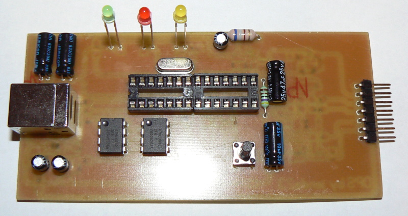
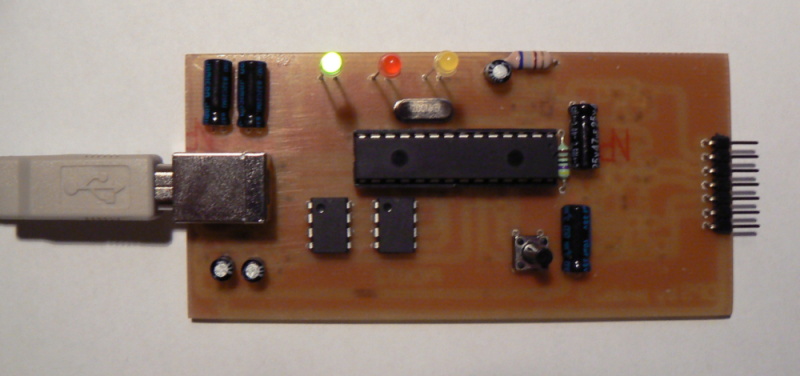
The main element is a modern powerful PIC18F2550 processor, controls all activities of the programmer to communicate with the PC, write to the EEPROM, write to the programmed processor, etc. The big advantage is that the CPU is right in itself contains a USB interface, so you can connect directly PC. He needs an integrated system HID driver, so no need to install another driver as the AVR programmer. The processor has a hinge PLL set to 96MHz which obtained by multiplying the 20 MHz crystal, USB own runs on 48MHz. Which is to support full speed communication. Furthermore, the involvement of two 24C512 EEPROM, the processor uses the system PICkit2 TO GO is a mode where the programmer to "send" custom firmware, which we later be programmed into one or more processors. The advantage is that we do not need a PC for programming, just napájíme programmer and program the button connected to the processor, all data on the programmer draws from these two EEPROM. To communicate with us using only the control software as well as three LEDs
GREEN (USB connect) - indicates a connection to the mains
YELLOW (Target) - indicates the power supply voltage for the programmed processor
RED (BUSY) - indicates activity Programmer
Another part of the drive voltage, this whole section is managed by the port RC2, then using the PWM controls the voltage in the range of 2.5 to 5V, set in the control software on your PC. PWM voltage fed to the integration of Article R28, C14 and OP1 is driven through the main MOSFET of which is sampled voltages for programmed processor (+ V_TGT). This tension is also excited by the drive to obtain 12V. It is controlled by the transistor T3 and the need for the processor generates a voltage based on the rectangular pulses at a frequency of about 30kHz. Due to the switching inductance occurs inducing tension that is added to 5V, the resulting voltage is rectified by diode D1 Shottkyho to ensure that the output size will be needed this tension is introduced feedback resistor divider R4, R11. Pokad this voltage is low, the software gives us the know buzz. Capacitor C5 filters the voltage that this was not rolling. The voltage is switched 12V PNP transistor T2 is controlled by the transistor T6. These transistors turn on voltage programování.Tranzistor T8 used to reset the processor when the application programmer as a debugger. Despite R1 is monitored supply voltage for programming the processor and also measured the function velikost.Bohužel T1, T4, T5, T7'm not entirely clear. Custom programming and ISPD ISPC leads are brought directly from the processor.
ISPD - the programmed data processor
ISPC - clock for programmed processor
T1 button serves to activate the bootloader, press the programming, and programming mode PICkit2 TO GO
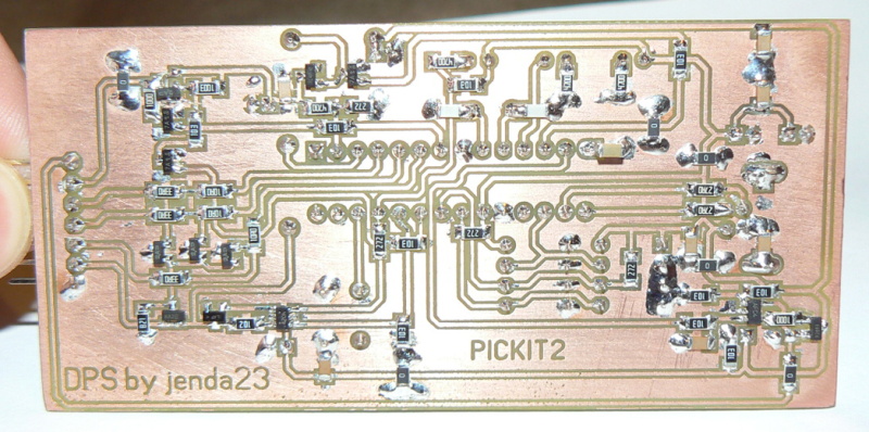
The PCB I made in the program SPRINT LAYOUT, is made in SMD.
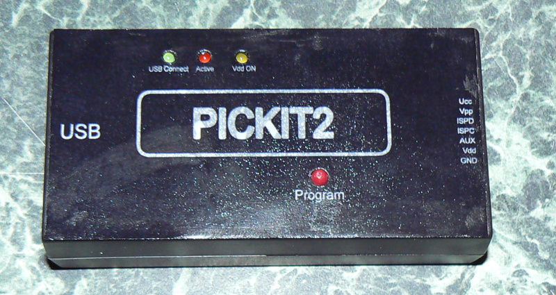
Mechanical design: the programmer is placed in a plastic box KP35, in front of the hole is bleeding for the USB connector and the second hole for the head of the programming connector.
Starting and software installation
1) After downloading the file PICKIT2.zip you'll see a set of "Bootloader", this file must load into the processor with another programmer. Thus we recorded the CPU "loader" which you already own frmware then downloaded to a PC via a USB port. For we have not finished programming the MCU.
2) Download the software PICkit2 (Version 2.50 or 2.60) installed it. Pokad we lack the necessary version of NET Framework is included instalačce and automatically prompts us to install.
There are reports that the software programmer can not be found, but how could we not joined it yet, but come on, the programmer is connected to the green LED programmer and we shall call "bubble" as PICkit2 HID devices. After installing the drivers, we are ready to upload custom firmware programmer. This is done as follows:
3) In the Tools tab, click on "Communication Check" program, so we got to know that we have connected the programmer
Subsequently, we have a program to find a programmer
4) then we are also "unlock" option to download the firmware on the programmer
5) click on this option we will offer a program that we have chosen the location of the firmware (which you have saved), select the file "PK2V023200"
6) will now begin downloading the firmware on the programmer
7) pokad firmware installation was successful, this appears
8) The programmer is logged and displayed in the program (ID, do not mind, it is set later, the first programmer is not connected)
Thus we successfully completed the installation of software and firmware programmer is ready for use in the next section we show how to calibrate the voltage set ID and show you a simple description of the PC interface.
Set ID and calibration
The programmer allows you to calibrate the voltage programmed for the processor, this voltage can be varied in the range of 2.5V to 5V. We will subsequently, in the "Tools" click on "Calibrate Vdd & Set Unit ID .. " and accelerates our guide
Clicked When we see the following window, voltmeter measure the voltage on the output and write to the relevant software, make the necessary correction.
The following is only a setting of that ID, which is basically an identifier Programmer
After you click "Finished" is set ID and calibration over
Another option to check if everything works fine in the "Tools" menu click on "Troubledhoot" and once again will open the wizard.
You can adjust the voltage from 2.5 to 5V and click on "test" this voltage is measured and shown
The next step is to check voltage Vpp should be around 12V
Finally, a test port for programming, can be either in or LOG0 log1 or tested 30kHz signal which generates the MCU
I just wanted to point out that the distribution of pins on this version of the programmer is not the same as the original !!!!!!!!!!
So now enough testing to verify the de vopravdová function, it is time to connect to the MCU programmer.
But first a little description of the software:
1) The checkbox "ON "turns on or off the permanent power supply for CPU
2) check mark "/ MCLR" says MCLR output to the third state (high impedance)
3) the "Read", "WRITE", "verify", "erase" is used to guide programming of the MCU, I do not have to explain that
After a successful connection to the MCU programmer and clicking on the "Check communication" we would have reported a programmer and software would have to inform us about the PIC chip has been found message "PIC Device found."
The only comment is that the programmer is able to detect the CPU type itself not to what family it belongs, so that families have to manually select the submenu "Device Family", then it is automatically detected by the MCU type. Otherwise we write message "No device detected". After selecting the families and detecting MCU and click on the "Read" the programmer should read contents of the processor. Pokad was successful reading see the following:
We will describe the additional features programmers like log analyzer, UART terminal, programmable ports, mode PICkit2 TO GO
1) The log analyzer and programmable ports
In this mode PICIKIT can function as a three-channel logic analyzer with a maximum sampling frequency of 1MHz, making it applicable to frekvnce to 500kHz. But watching the SPI or I2C enough.
Logic Analyzer, run the "Tools" We use two schemes
A) Three freely programmable ports
Each of the three ports can be selected as input or output, the choice of input is read, the log level and is displayed in the appropriate box to choose the output is switched according to our preset value in the box.
B) as a 3-channel logic analyzer
2) a UART terminal
3) The regime PICkit2 TO GO
Run from the "Programmer"
Putting the programmer in preparing this scheme we perform Wizard
Now we set where the programmer supplied
The next step is to download the firmware from MCU
After clicking on "Download"
After successfully copying the firmware to the flash EEPROM yellow LEDs
Followed by setting the error messages are indicated by flashing red LED as the programmer does not have a PC with which it reported an error.
And this is a programmer in the "To Go", we will exit this mode when connected to a PC using "C Communication"
I think it ends with a description of the neediest cases what programmers can do.

|
|
|
| |
Accurate LC Meter
Build your own Accurate LC Meter (Capacitance Inductance Meter) and start making your own coils and inductors. This LC Meter allows to measure incredibly small inductances making it perfect tool for making all types of RF coils and inductors. LC Meter can measure inductances starting from 10nH - 1000nH, 1uH - 1000uH, 1mH - 100mH and capacitances from 0.1pF up to 900nF. The circuit includes an auto ranging as well as reset switch and produces very accurate and stable readings. |
|
PIC Volt Ampere Meter
Volt Ampere Meter measures voltage of 0-70V or 0-500V with 100mV resolution and current consumption 0-10A or more with 10mA resolution. The meter is a perfect addition to any power supply, battery chargers and other electronic projects where voltage and current must be monitored. The meter uses PIC16F876A microcontroller with 16x2 backlighted LCD. |
|
|
|
60MHz Frequency Meter / Counter
Frequency Meter / Counter measures frequency from 10Hz to 60MHz with 10Hz resolution. It is a very useful bench test equipment for testing and finding out the frequency of various devices with unknown frequency such as oscillators, radio receivers, transmitters, function generators, crystals, etc. |
|
1Hz - 2MHz XR2206 Function Generator
1Hz - 2MHz XR2206 Function Generator produces high quality sine, square and triangle waveforms of high-stability and accuracy. The output waveforms can be both amplitude and frequency modulated. Output of 1Hz - 2MHz XR2206 Function Generator can be connected directly to 60MHz Counter for setting precise frequency output. |
|
|
|
BA1404 HI-FI Stereo FM Transmitter
Be "On Air" with your own radio station! BA1404 HI-FI Stereo FM Transmitter broadcasts high quality stereo signal in 88MHz - 108MHz FM band. It can be connected to any type of stereo audio source such as iPod, Computer, Laptop, CD Player, Walkman, Television, Satellite Receiver, Tape Deck or other stereo system to transmit stereo sound with excellent clarity throughout your home, office, yard or camp ground. |
|
USB IO Board
USB IO Board is a tiny spectacular little development board / parallel port replacement featuring PIC18F2455/PIC18F2550 microcontroller. USB IO Board is compatible with Windows / Mac OSX / Linux computers. When attached to Windows IO board will show up as RS232 COM port. You can control 16 individual microcontroller I/O pins by sending simple serial commands. USB IO Board is self-powered by USB port and can provide up to 500mA for electronic projects. USB IO Board is breadboard compatible. |
|
|
|
|
ESR Meter / Capacitance / Inductance / Transistor Tester Kit
ESR Meter kit is an amazing multimeter that measures ESR values, capacitance (100pF - 20,000uF), inductance, resistance (0.1 Ohm - 20 MOhm), tests many different types of transistors such as NPN, PNP, FETs, MOSFETs, Thyristors, SCRs, Triacs and many types of diodes. It also analyzes transistor's characteristics such as voltage and gain. It is an irreplaceable tool for troubleshooting and repairing electronic equipment by determining performance and health of electrolytic capacitors. Unlike other ESR Meters that only measure ESR value this one measures capacitor's ESR value as well as its capacitance all at the same time. |
|
Audiophile Headphone Amplifier Kit
Audiophile headphone amplifier kit includes high quality audio grade components such as Burr Brown OPA2134 opamp, ALPS volume control potentiometer, Ti TLE2426 rail splitter, Ultra-Low ESR 220uF/25V Panasonic FM filtering capacitors, High quality WIMA input and decoupling capacitors and Vishay Dale resistors. 8-DIP machined IC socket allows to swap OPA2134 with many other dual opamp chips such as OPA2132, OPA2227, OPA2228, dual OPA132, OPA627, etc. Headphone amplifier is small enough to fit in Altoids tin box, and thanks to low power consumption may be supplied from a single 9V battery. |
|
|
|
|
|
Arduino Prototype Kit
Arduino Prototype is a spectacular development board fully compatible with Arduino Pro. It's breadboard compatible so it can be plugged into a breadboard for quick prototyping, and it has VCC & GND power pins available on both sides of PCB. It's small, power efficient, yet customizable through onboard 2 x 7 perfboard that can be used for connecting various sensors and connectors. Arduino Prototype uses all standard through-hole components for easy construction, two of which are hidden underneath IC socket. Board features 28-PIN DIP IC socket, user replaceable ATmega328 microcontroller flashed with Arduino bootloader, 16MHz crystal resonator and a reset switch. It has 14 digital input/output pins (0-13) of which 6 can be used as PWM outputs and 6 analog inputs (A0-A5). Arduino sketches are uploaded through any USB-Serial adapter connected to 6-PIN ICSP female header. Board is supplied by 2-5V voltage and may be powered by a battery such as Lithium Ion cell, two AA cells, external power supply or USB power adapter. |
|
200m 4-Channel 433MHz Wireless RF Remote Control
Having the ability to control various appliances inside or outside of your house wirelessly is a huge convenience, and can make your life much easier and fun. RF remote control provides long range of up to 200m / 650ft and can find many uses for controlling different devices, and it works even through the walls. You can control lights, fans, AC system, computer, printer, amplifier, robots, garage door, security systems, motor-driven curtains, motorized window blinds, door locks, sprinklers, motorized projection screens and anything else you can think of. |
|
|
|