Home   |   Electronic Store   |   Electronic Blog   |   Electronic Schematics   |   Tutorials   |   Downloads  |   Links   |   Contact

 Electronic Schematics
FM Transmitters
PLL Synthesizers
Stereo Encoders & Decoders
Antennas
FM Receivers
Audio / Amplifiers
Power Supplies
AC/DC Inverters AC/DC Converters
Battery Chargers
Remote Control
PC Related
Test & Measurement
PIC / ATMEL / AVR
USB Circuits
Telephone Related
LED
Miscellaneous Circuits
Stepper Motors

 Latest Schematics
BH1415F FM Stereo PLL Transmitter
PIC USB Interface with FT245
Low Pass Filter For FM 88-108 MHz
BH1415F FM Stereo PLL Transmitter
8 Channel RF Remote Control
Wireless PLL Stereo FM TX with LCD
USB Sound Card with PCM2702
ATmega48/88/168 Development Board
CMoy Headphone Amplifier
Fast PIC NiMH / NiCd Battery Charger
1Hz to 1MHz Function Generator with XR-2206 IC
2W RF Amplifier For 24/23 CM
Intelligent NiCd/NiMH Battery Charger
RS232 Serial to USB Converter
Wireless Temperature and Humidity Sensor with USB
Digital VGA Switch
Serial Port Professional PIC Programmer
DIY Bench Power Supply
LED Bargraph Optical Tachometer
NiCd Charger with Thermal Peak Detection
Plane Motor Controller with High-Rate ESC, BEC and Brake
Ultrasonic Parking Assistant
USB Powered AA NiMH and NiCd Battery Charger
TTL <> RS232 Converter
Serial Port I/O Expander
RS232 Booster
PIC Programmable Security System
FANCY LEDS
Solar Panel Controller
 
 Schematics  >> 


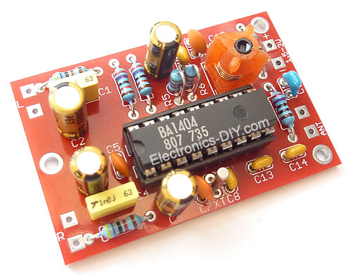
BA1404 HI-FI Stereo FM Transmitter
The above FM transmitter design is a result of many hours of testing and tweaking. The goal was simple; to test many existing BA1404 transmitter designs, compare their performance, identify weaknesses and come up with a new BA1404 transmitter design that improves sound quality, has very good frequency stability, maximizes transmitter's range, and is fairly simple for everyone to build. We are happy to announce that this goal and expectations have been met and even exceeded.


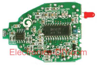
BH1417 PLL Stereo Transmitter
This is the latest BH1417 FM Transmitter design from RHOM that includes a lot of features in one small package. It comes with pre-emphasis, limiter, stereo encoder, low pass filter, PLL rock solid frequency transmission and RF output buffer.
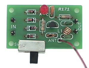

Single Chip FM Transmitter
Simple to build once chip FM Transmitter that requires only 3 - 5V to operate. This transmitter links your home-entertainment system to a portable radio that can be carried around the house and into the back yard. For example, you can play music on the CD changer in your living room, and listen to it on a portable radio by the back-yard barbecue.


TX200 High Quality 200mW FM Transmitter
Here is the latest and greatly improved TX200 VFO/VCO FM transmitter. The most versatile transmitter to date that can be turned into high fidelity stereo PLL based 200mW FM transmitter. It is a perfect circuit for transmitting your music around the house and yard.


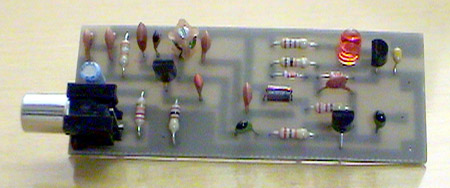
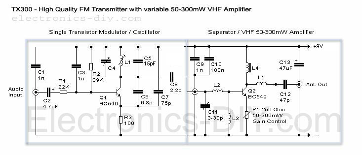
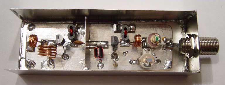
TX300 300mW FM Transmitter
Here it is a brand new TX300 FM transmitter. The amplifier has exactly the same architecture as TX500 with the difference that TX300 has only one stage variable VHF amplifier.


TX500 - 500mW FM Transmitter
The TX500 is a simple to build 500mW FM Transmitter. It consists of three blocks; modulator / oscillator, two stage 500mW VHF amplifier and LED based power meter. The TX500 allows to transmit audio signals to FM band at frequencies from 88 MHz to 108 MHz. Due to the very low power consumption of less than 100mA the circuit may be perfectly powered by using 9-12V battery or power supply if you prefer. The circuit has been divided into separate stages so that it is be better for everyone to understand how every part works independently.


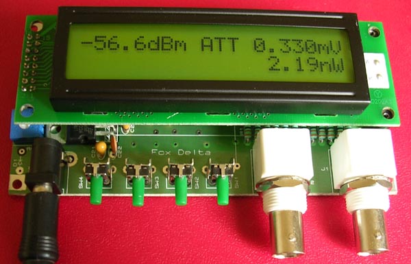
0-500MHz PIC16F876 RF Power Meter
RF Measurement has been an expensive work so far the cost of measuring instruments are concerned. RF Meter is based on PIC16F876 microcontroller, AD8307 and 2x20 LCD display. Full documentation is included.


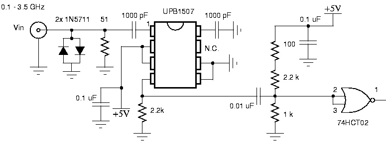
0.1 - 3.5GHz Prescaler
This handy prescaler divides input frequency by 1000. It takes maximum input frequency of 3.5GHz and converts it into 3.5MHz that may be measured using standard frequency meter.


1 Watt RF Amplifier
This is a universal 1 Watt RF class C amplifier that is ideally suited for low power FM transmitters. Input should be at least 100mW to achieve 1W output. It is recommended to enclose the amplifier in a metal case.


1.5W VHF Amplifier
This project will explain the basic function of a class-C transmitter. I will explain how to dimension a transmitter and the purpose of the different components. I will also explain how you can build a 1.5W PA transmitter. The project will include PCB, components and instructions how to make coils, assembly and testing.


100W FM AMPLIFIER
This Power amplifier is equipped with a bipolar transistor,the famous MRF317 As lots of FM amplifier application ,the power transistor is in a C class bias. All the impedance networks (Input & Output) have been determined by using the software: Mimp.EXE. A 9 elements low pass filter ensures that we meet at least a 60 dB rejection from the carrier.(RF Simulation with RFSIM99) The FM amplifier has a 10 dB gain with a 60 to 65% efficiency. The Input VSWR is around 1.4 and there's no problem to reach the max power in all the FM band..


15dB UHF TV Antenna Booster
This is an UHF band TV antenna preamplifier circuit With 15dB gain to build easily. It is formed based on BF180 UHF Transistor. The first stage is an band pass filter constructed by the C1, CV1, L1, L4, C7 and C3, the second stage is a base-common voltage amplifier with low input impedance to match. Build the L1 ~ L4 as air core coil to obtain high Q-Factor. After assembling, pack it into a proper metallic box and connect the ground of the circuit to the box to reduce noise effect.


1GHZ Frequency Meter
This is 1GHz frequency counter with 100KHz resolution. Meter is built in around PIC16F84A microcontroller and SAB6456 / U813BS prescaller.


1W Linear FM Booster
This RF Amplifier is used for boosting small fm transmiters and bugs. It use two Philips 2N4427 and its power is about 1Watt. At the output you can drive any linear with BGY133 or BLY87 and so on. Its power supply has to give 500mA current at 12 Volts. More voltage can boost the distance but the transistors will be burned much earlier than usual.! In any case do not exceed the 15Volts. The Amp offers 15 dB in the area of 80Mhz to 110 Mhz. L4, L5, and L6 are 5mm diameter air coils, 8 turns, with wire 1mm wire diameter.An easy project, with great results.


1W portable PLL transmitter
This small FM transmitter includes a limiter, a microphone amplifier and a PLL digital tuning. All the parts are placed on one circuit board. The RF power is switchable between 1W and 0,2W. The schematic diagram is divided into three parts: RF part (numbered from 1), PLL (numbered from 30) and audio part (numbered from 50).


1W RF Power Amplifier for iPOD Stereo FM transmitters
This project explain how you can build and connect a powerful 1W amplifier to your FM transmitters. A perfect solution for those wishing to listen to their favorite tunes in the car, house, garden, school, campus, party, you name it.... Why not share your music with every one else in your city!


20W FM Amplifier
This Power amplifier is equiped with two Philips bipolar transistors : the BLV10 & BLW87. As lots of FM amplifier design, the RF transistors are in a class C bias. The FM amplifier has a 21 dB gain with a 55 to 65% efficiency.


25W RF amplifier
RF amplifier with 25W of power for 88-108MHz FM transmitters.


2W RF Amplifier For 24/23 CM
This page describes TX ATV Transmitter for 23 cm with output adjustable from 100 to 250mW.


300 MHz Prescaler
A preamp that drives the CMOS counter input and a divide by 10 prescaler to extend the range of A Little More Serious Frequency Meter. The MCT10280 prescaler can be set to divide by 80, 40, 20, or 10, as a function of which pins are tied to the power supply. I set this one to divide by 10 since it is adequate for my needs, and the mental calculation of multiplying the meter reading by 10 is not taxing. One problem with the MCT10280 is that if it doesn't have an adequate input, the output is very noisy, which shows up as counts in the couple MHz range on the frequency meter. This noise shows up if the signal amplitude the signal frequency is too low. For this reason, I only intend to use the prescaler with inputs between 10 MHz and 300 MHz.


30W VHF FM Amplifier for 88 - 108 MHz with BLF245 MOSFET
The achievement of this 30-watt amplifier has been designed to take place on a heatsink microprocessor PC equipped with its fans, the advantage of this method of cooling has been selected for the fact that it is not very common and expensive. The size of the printed circuit will adapt quite easily to the type of heatsink as you have available, if possible, because in many cases, those of recovery, the fans have already lived and the price of a model remains very affordable.


3V FM Transmitter for 88MHz to 108MHz
The important part of the circuit is formed of the Colpitts type oscillator. C3,C4,C5,C6,CD1-CD2 and L1 determines the frequency. BF982 and dual gate MOSFET are active parts in oscillator. When the input impedance of the MOSFET gate inputs are high, LC tank is not affected. However transistors force the LC tank and cause phase shift. Two driver stages are added to isolate the antenna from oscillator. First stage (BF199) amplifies the low signal of the oscillator and works as a constant load. The second stage (BFR90) amplifies the signal going through the antenna some more. A short copper wire can be used as an antenna here. Attaching a large antenna to this circuit is unnecessary because the output power is low.


400mW VCO FM transmitter
With good antenna (dipole placed outdoor and high) the transmitter has very good coverage range about 500 meters, the maximal coverage range is up to 4 km.


5 Watt UHF TV Amplifier
This small circuit is a Linear amplifier for driving small UHF TV transmitters. Its gain is 7dB and can amplify a signal between 450-800 MHz. You can drive the circuit with 1 to 1,5 Watts signal. Better use double layer PCB with the second layer connected to earth. Use a stabilized power supply 25 volts and at least 5Amps. The transistor case is the SOT-122A and be careful because the transistor is very toxic for your health. Tuning can be achieved turning the two variable capacitors. Do not forget to use heat sink for both transistors, specially for the BLW89 and it would be better if you place a small fan as well.


8W PLL Stereo Transmitter with LCD
Very stable FM transmitter based on TSA5511 synthesizer. Frequency is performed with three buttons through PIC16F84 microcontroller. Frequency is displayed on 16x1 LCD.


BandPass Filter
This bandpass filter is in fact a combined high- and lowpassfilter. The first stages are a highpass (f>70MHz) and the last stages a low pass (f<180MHz). The lost of this filter is several watts when driven with 20[Watts], but the output signal is (when adjusted with a spectrum analyser) very clean.


BH1415F FM Stereo PLL Transmitter
Transmitter power amplifier, the output signal from BH1415F by 2 SC9018, 2SC3355, 2SC2053 amplified signal can reach more than 500 mW, adjusting well to achieve greater power. Measured by the pull rod antenna used to be launched in the open 800 meters above. Uses external antenna will be launched even further. attention in 2053 need to be installed and tested at the load connected to leave, or else very easily burn 2053, 50 European amateur production of 2 W can be used instead of resistance. installed and tested at three levels circuit can be installed and tested.


BH1415F FM Stereo PLL Transmitter
This is FM PLL Stereo based BH1415F IC from Rohm, it's has built in PLL and Stereo Encoder. You can download the schematic, pcb layout and Hex code. The transmitter menu display with LCD, and this have step 100Khz, 200Khz,.....1000Khz and have Mode menu (stereo/mono). In Action, LCD Display can solder directly on the bottom.


CB Transmitter
For the regulation it needs a voltmeter (with needle better) and charge 50W/5W. Connect charge 50W in the place of aerial, with the voltmeter in the exit voltmeter. Be supplied the transmitter with + 12V. It will be supposed we have consumption between 0,7-1A. With a screwdriver we regulate the core of inductor L1/L2 and later the variable C6 until we see the biggest tendency. We connect the microphone and speaking we observe the clue in the multimeter. If all have become right will be supposed the tendency, speaking, to go up roughly 30-35%.


Low Pass Filter For FM 88-108 MHz
Filter used for eliminate unwanted harmonic frequency at second and third. Notch filter, Band Pass Filter (BPF), and High Pass Filter (HPF) sometime combined in constructing LPF design. Schematic below for FM Broadcast Lowpass Filter 88-108 MHz. It has been tested with a good result. Note : Make the coils at 74 nH and trim them to adjust exact value.


LowPass Filter
The schematic you find here comes from another site on the internet, but because it's on so many sites, we don't know who actually designed it. However it's a nice one. Capacitors: C1,C4 22pF cer. C2,C3 51pF cer. Coils: L1,L2,L3 #18 bus wire, 1/4"diameter, 3 turns * Form the leads from the capacitors as shown in the little figure below. Then solder them from the pad to the outside ground area. * Be sure that the turns from the coil are seperated by the same distance as the diameter of the wire * Form the leads from the coils as shown in the little figure below. Then solder them in place. * Place the filter in a metal box, with rf-connectors on both ends ( SO239(=PL259), BNC or N-connectors)


MC145170 PLL FM Transmitter
In order to simplify the transmitter design, we've used the new pll circuit from Motorola :the MC145170. This PLL includes the prescaler and a serial standard bus called SPI.


PLL Exciter
This is a PLL controller that works with the VCO/Modulator that I designed. Use these two modules together for a complete baseband-capable exciter unit. This PLL controller features a rock-stable crystal controlled reference, in conjunction with a programmable dividing network which allows the transmitter to be tuned in 100Khz steps from 79.9Mhz to 109.7Mhz by means of digital thumbwheel switches.


PLL FM Transmitter
This new FM transmitter is very simple and doesn't need any RF tuning. First of all ,we have used an integrated VCO: The POS150 from Mini-circuits. This excellent RF circuit covers all the FM Band in a voltage range of 4V to 8V. The Kvco factor is very stable all over the FM band, consequently, we have applied the BF signal directly on the control voltage line coming from the PLL.


Prescaler with Counter
Digital frequency counter is being used for wide range of applications. Digital frequency counter extensively uses digital circuits and hence fairly good knowledge of digital circuits and of digital integrated circuits is required to understand the operation of the frequency counter. However a person who is not familiar with any electronics circuits and experiments has in written this article.


Radio Remote Control using DTMF
Here is a circuit of a remote control unit which makes use of the radio frequency signals to control various electrical appliances. This remote control unit has 4 channels which can be easily extended to 12. This circuit differs from similar circuits in view of its simplicity and a totally different concept of generating the control signals. Usually remote control circuits make use of infrared light to transmit control signals. Their use is thus limited to a very confined area and line-of-sight. However, this circuit makes use of radio frequency to transmit the control signals and hence it can be used for control from almost anywhere in the house.


Ramsey 25 BA1404 Stereo FM Transmitter
Stereo FM transmitter based on BA1404 and 145170 frequency synthesizer IC.


Remote control using VHF modules
A few designs for remote control switches, using VG40T and VG40R remote control pair, are shown here. The miniature transmitter module shown in Fig. 1, which just measures 34 mm x 29 mm x 10 mm, can be used to operate all remote control receiver-cum-switch combinations described in this project. A compact 9-volt PP3 battery can be used with the transmitter. It can transmit signals up to 15 metres without any aerial. The operating frequency of the transmitter is 300 MHz. The following circuits, using VG40R remote control receiver module measuring 45 mm x 21 mm x 13 mm, can be used to: (a) activate a relay momentarily, (b) activate a relay for a preset period, (c) switch on and switch off a load.


RF Buffer Stage
This bufferstage is intended to be used after a BF900 or BF199 (even a BF245) oscillator. It delivers several milliwatts and is perfect to drive a 2N2219 or 2N4427. Be sure the coils are really round and can "see" each other: place metalplates between the coils. The supply voltage is around 12V (typ. 13,8V).


RF Power Meter
RF Power Meter for QRPers


RF Preamplifier
Input needs only several mWatts (e.g. BF900) -> 300 mWatts OUT. This schematic is a often used buffer. It's easy to build, clean and cheap. When you want even more power, you can replace the 2N2219a by a 2N4427 or 2N3553. You can lower the output by adding a little resistor (10..47 Ohm 1/2W) in the emitter line of the 2N2219a.


SAA1057 PLL Synthesized FM Transmitter
The functioning of all is provided by a microcontroller from MICROCHIP "PIC16F84" which provides support for buttons, LCD 2 lines of 16 characters and the circuit pll "SAA1057. The VCO is entrusted to the transistor Q8 associate of his two diodes varicaps "BB109, a floor buffer Q7 separates the VHF signal obtained in two ways, on the one hand to Q9 to enslave loop phase and on the other hand to the Q5 and Q6 together which takes care to amplify the signal before attacking Q11, a "BFR96" which plays the role of HF switch via a timer "NE555" which receives information from the push and "SAA1057" ensuring HF cutoff in the event of failure of a locking or unlocking of the pll.


Simple RF Power Meter
Here is a simple set up which will enable them to measure the out put power of their transmitter. All that they require is a good multimeter which has a sensitivity of 20k ohms/4 Watts which is adequate for low power transmitters. Many beginners trying out their skill with QRP TX, for the first time have to overcome many problems before they are able to come on the air. On usual complaint is that, every thing is working fine but the signal is not going out.


Telephone FM Transmitter
This FM transmitter attaches in series to one of your phone lines. When there is a signal on the line (that is, when you pick up the handset) the circuit will transmit the conversation. In particular it will radiate from the phone line itself. It is a passive device - there is no battery. It uses the signal on the phone line for power. No aerial is needed - it feeds back the RF signal into the phone line which radiates it in the FM band. The frequency of transmission may be adjusted by the trimcap.


TV Transmitter
A VHF band TV transmitter using negative sound modulation and PAL video modulation. This is suitable for countries using TV systems B and G.


UHF-TV Preamplifier
UHF-TV Preamplifier


USB RDS Coder Board using ATmega32
This board is a RDS coder using an ATMEL AVR ATmega32. This board can be controled by a RS232 link, USB interface or SPI. TA data is displayed wiyth a LED and can be controled by : - Hardware input - RS232 - USB - SPI (not yet implemented)


VERONICA 1W - 5W FM Transmitter
The Veronica is an easy to build and tune transmitter for the FM band. It's known for it's stability and clean signal, does not use any IC's or similar specialized parts, and it has a built-in tuning aid that makes it possible to tune it with no extra equipment. It's available in two versions, 1 and 5 watts.


Veronica 1W PLL FM Transmitter
The VERONICA transmitter is a very stable, powerful, and high quality FM emitter. Thanks to a PLL, the output frequency is controlled with DIP switches. Output power is approximatively 1W with a single regulated 13.8v supply ! (see specifications) Features : * High RF output power : 1W * Full 87.5-108MHz range (100KHz increment). * Very stable output frequency : Crystal reference & Phase Locked Loop. * Professional input bandwith (fully RDS compatible ) * No complex tuning needed. * High quality PCB * Full documentation & construction details available


VHF Audio Video Transmitter


VHF/UHF Prescaler
The recommended Prescaler is ridiculously simple. It consists of just one IC, a TV tuner prescaler, the Philips SAB6456A, which can divide by 64 or by 256. This chip is widely available both new and in the surplus market at much lower prices than conventional divide by 10 prescalers.


VHF/UHF TV Modulator
Simple oscillator that generates a frequency in the VHF or UHF region. The oscillator is modulated with the video signal and the modulated carrier wave thus generated is fed into the TV set's aerial input via a cable. Then all that remains to do is tune the TV to the correct frequency.


Video/Audio Wireless Transmitter
Television signals operates as two separate transmissions. One for the video and the other for sound. And just like our project, two different devices are going to be built.


Wide Band RF Amplifier for 10MHz - 500MHz Input
This is a wide band amplifier cicuit which is suitable for the frequencies between 10MHz and 500MHz. Wide band amplifiers are used in communication receivers, RF measuring equipment and tons of other devices. The circuit described here uses a state of the art transistor to get maximum performance at high frequencies. It can be used as a low noise pre-amplifier due to his low noise characteristics.


Wireless PLL Stereo FM TX with LCD
Now you can use your MP3 Player to listen your favorite tunes through any FM stereo receiver. Wireless FM transmitter wirelessly connects portable music players to your car or home stereo quickly and easily. Just plug the FM Transmitter into the headphone jack of your MP3 or any audio source including iPOD, PDA, CD Player, Cassette player or connect it to your PC or laptop computer. Tune your card stereo or receiver to the clearest FM frequency, and enjoy your digital music with full sound and convenience.


Electronics-DIY.com © 2002-2008. All Rights Reserved.