 Traditional Method
A composite stereo signal, as transmitted by FM radio stations, is composed of at least three parts: A base band mono signal, a double sideband channel difference signal, and a pilot carrier. The signal composition is somewhat analogous to an NTSC composite color television signal. I said at least three parts because some stations transmit other things such as data and background music that our normal FM receivers do not decode.
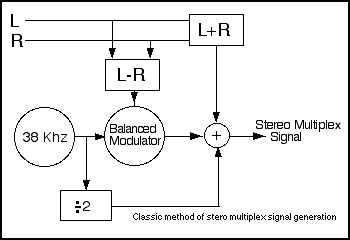
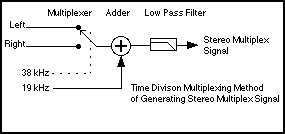
The base band signal falls between 30 Hz and 15 kHz. This is the part of the audio signal that comes out of the speaker on a mono receiver, In the classical encoder, it is made by simply adding the Left and Right channel audio signals together, and is often referred to as L+R.
A double sideband channel difference signal, often referred to as L-R is also transmitter. The information in this signal is the difference between the signals in the Left and Right channels. In the classical encoder, the channel difference signal is made by subtracting the Right channel audio signal from the Left channel audio signal. The channel difference signal is then combined with a 38 kHz carrier in a balanced modulator to form a double sideband signal centered at 38 kHz.
The third signal, a pilot carrier at 19 kHz, exactly half the frequency of the carrier used to generate the 38 kHz double sideband signal. The 19 kHz signal is used to regenerate the missing 38 kHz carrier in the receiver and this 38 kHz carrier is used to demodulate the double sideband signal.
The three separate signals are not intended to affect each other. Careful filtering can minimize undesirable interactions, most of which would be some kind of beat between the 19 kHz pilot signal and the Left and Right channels and their products.
I fiddled with the classical encoder on paper a number of times over the years. The designs always had all sorts of neat blocks - an oscillator and frequency divider, a balanced modulator, one or more summing amplifiers and a few of filters. In all, something that would not result in a home project that would be easy to duplicate. The 38 kHz oscillator could be made with a 74HCT60 oscillator/counter chip and a 38 kHz crystal. The balanced modulator could be made with a Giblert cell multiplier for something nice, or a set of transmission gates switching complimentary audio signals, or ever with resistor networks being switched by micro controller I/O pins. The L+R function could be achieved with a pair or resistors and the L-R signal by a simple op amp circuit. If an op amp were to be used to sum all the signals together, it would have to be quite good - passing the 38 kHz and its sidebands and maintaining phase with respect to the baseband L+R signal. I had bought some pretty nice op amps in anticipation of using them, until I finally understood the simpler method, described below.
Simpler Approach
I came across a very simple and robust stereo encoder project on Harry Lythall website. Harry amateur radio call sign is SM0VPO, and he can be readily Goggled. The circuit was simple, it was elegant, and I did not have clue as to how it worked. After coming back to his project several times, I realized that I had seen a write-up of this technique, but I had not understood it well enough to appreciate what I was looking at.
The technique that lends itself to such an elegant implementation is explained at:
http://web.archive.org/web/20060214011755/http://transmitters.tripod.com/stereo.htm <== This will open a new window. The original link, http://transmitters.tripod.com/stereo.html, stopped working within days of the first publication of this web page, and I am grateful to Internet Archive for making it available to us.
What I added to Harry encoder was a slight twist. That of using an AVR micro controller to replace the oscillator/counter and the analog transmission gates. And that is what this circuit does. A cheap micro controller, an NPN transistor and a handful of passive components is all that it takes to make a simple stereo FM transmitter.
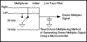
This simpler approach calls for simply switching the audio channel between the Left and Right inputs. Each channel is sequentially connected for one half cycle of the 38 kHz carrier. That produces both the 38 kHz double sideband signal and the baseband signal. A low pass filter reduces the splatter, resulting from harmonics of the switching, on adjacent radio channels. I understand that this is how one of the low cost single chip encoders works. It makes sense, this method relies on matching of components and no precision circuitry. Its nearly fool proof.
Switching in this way generates a 38 kHz double sideband signal and passes both L and R through the baseband. L and R have opposite polarities in the decoder because L is allowed through to the transmitter on one half of the 38 kHz cycle and R is allowed through on the other half. When L and R are equal, the two signals average out to zero over each cycle. It could not be simpler.
 Circuit
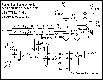
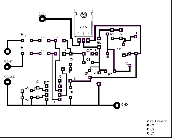
The switch to ground is actually implemented by two separate I/O pins on a micro controller.
The only tricky part is achieving the 2:1 analog multiplex function with a micro controller. This needs to be done without switching the DC level of the signal, because that would cause the 38 kHz carrier to feed through. CMOS Micro controller I/O ports can switch between high impedance and low impedance states. But when in the low impedance state, the pin can only be at either ground (logic low) or at the positive power supply (logic high). That means that the switching action must take place by mixing the Left and Right signals resistivity, then basically shorting out one, then the other in alternation. To maintain the condition that the switch not changing the DC level of the signal, the signal will have to be centered around ground or the positive power supply. I chose ground since the input signal would be referenced to ground.
What the data sheets do not tell us is that the FET that drives the output pin low, an N-Channel FET, is pretty good a sinking current from signals above ground and sourcing current from signals below ground. Let me say that last part again: The N-Channel FET that drives the output pin can shunt signals below ground to ground. It is very much like a low value resistor that can be turned on and off. When the I/O port is in a high impedance state, if the signal tries to swing too far below ground, either the ESD protection device on the I/O pin or the parasitic diode that is intrinsic to the FET will conduct, clipping the signal. In this circuit, noticeable clipping at the I/O pin starts at several hundred millivolts below ground.
Since the FM transmitter in this circuit only needs a few tens of millivolts to attain satisfactory modulation, there is no need for amplification of the output of the multiplexer. There is more about modulation sensitivity in the part of this section that deals with the transmitter circuit.
To perform the switching between high impedance and low impedance to ground, the firmware zeros to the corresponding port registers registers, then at appropriate times, it clears the corresponding data direction register bits to make a given pin a high impedance, and at the appropriate times, the firmware sets the corresponding data direction register bits to make the a given pin a low impedance to ground.
This is about as simple of a build-it-yourself stereo transmitter as you can make. The pin assignments in the circuit above apply to the AT90S2323, ATTINY12, and ATTINY25.
Looking at the schematic in figure 4, the micro controller derives its timing from a 6 MHz crystal. 6 MHz is not an exact integer multiple of 19 kHz. In fact, it is the 315.7894th harmonic of 19 kHz. But there is no need to worry - we are talking analog here. I just count down by 316 and call it close enough, because the difference is only 0.06%. I used 6 MHz because I have a bag of them on hand. If you wanted to, you could use a crystal that is an exact integer multiple of 19 kHz. By the way, even higher frequency clocks can get you smaller errors. A 20.000 MHz crystal gets you only 0.04% error - about the same tolerance as many microcontroller crystals -just remember to modify the firmware to accommodate the different clock rate.
One might ask if using a micro controller to simply replace an oscillator, counter, and some transmission gates is kind of a waste of a good processor. It frustrates me to let most of a very competent RISC processor spend most of its time in timing loops and doing trivial bit twiddling, but when looking at the alternatives, use of a micro controller reduces the parts count, it is easily obtainable, and in very many cases, a less expensive solution than most of the other solutions available.
The Left and Right signals are AC coupled through C1 and C2, respectively. The purpose of AC coupling is remove any DC component of the source signal to allow the signals at the U1 (the AVR) I/O pins to operate symmetrically around ground.
At every half cycle of the 38 kHz clock rate, either U1 pin 7 or U1 pin 5 is grounded, while the other pin is left floating, which allows one signal at a time to get through to the input of the transmitter.
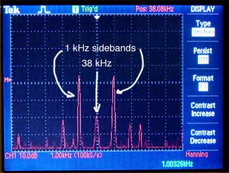
A 19 kHz square wave pilot signal is provided from U1 pin 6. Since the average DC level at pin 6 is +2.5 volts, a small capacitor is placed in series to keep this DC component out of the modulator (consisting of U1 pins 7 and 5), so there will not be any 38 kHz carrier.
All three of the signals - Left, chopped by 38 kHz, Right, chopped by 38 kHz of opposite phase, and a low level pilot signal are resistivly mixed at C4. I used the stereo indicator on my portable FM radio to find the value of R5, which in turn sets the amount of pilot signal in the composite signal, then I doubled the signal level. This should be more than enough, but feel free to decrease the value of R5. Cutting its value in half should not result in too much signal for the receiver.
The critical purpose of C4 is bypassing the base of the common base oscillator, Q1, to ground. The value was chosen so that the 38 kHz double sideband signal would not be rolled of significantly. I first calculated the maximum permissible value of C4 and then used the next smaller available size capacitor. After that, I tested it by trying a capacitor a little larger than the maximum calculated value and then then listening to a piece of music that features high frequency sounds moving from left to right. The larger capacitor significantly affected the separation of the higher frequency signals. The .001 uf capacitor shown in the schematic had no audible effect, and that is good because it was not supposed to.
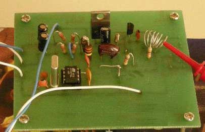
Simple circuit, the workhorse of the home brew wireless microphone projects, was pressed into service for the very reason that it is so popular with hobbyists: it does not require very many parts, it can be built with or without a printed circuit board, and usually actually works with enough tweaking.
In the transmitter, C3 decouples the base to ground through C4. C7 Can be a few pf above or below 5 pf without throwing things terribly out of whack. Try to keep the variable capacitor, C6, small. If you can only find larger capacitors, say 10 to 45 pf, put a 10 or 12 pf fixed capacitor in series with it. Its important to keep this part of the capacitance of the resonant tank as low as possible. If you do not have a suitable variable capacitor, you can always just put in a 5 pf fixed capacitor and rely on your ability to tune the circuit by stretching and distorting L1.
Q1 is a common 2N4401, and it exhibits a collector to base capacitance change of about 1.5 pf per volt. This is higher and better for this application than what you would get from high frequency transistors with lower output capacitance. The more of the tank capacitance that comes from Q1 collector-to-base capacitance, the more frequency modulation of the transmitted signal you will get for a given audio level. Since the stereo modulator can only handle several hundred millivolts peak-to-peak without distortion, this sensitivity is important.
I made L1 by winding 7 turns of #22 Beldsol copper magnet wire around the smooth part of a 1/4 inch drill bit (a trick mentioned by the legendary Harry Lythall), and then slipped the coil off the drill bit. I was shooting for the lower part of the FM band. Once the coil was wound and installed, I put C6 in the center of its range and then stretched and bend the coil until I could hear the transmitter on my FM radio tuned to the only quiet spot on the dial here, 93.3 MHz. If you want to use this at the high end of the FM broadcast band, you might want to try using only 6 turns.
Another trick for winding coils like this, that have to maintain their shape without a coil form, is to cut off a piece of wire a little longer than would be needed for the coil, then holding each end of the wire with a pair of pliers, stretch the wire slightly to orient the grain so that the wire tends to stay straight. When you wrap the wire around the drill bit, it will tend to hold its new shape instead of trying to spring back to its old shape. Be careful how you hold the wire while stretching it -you would not want to hit yourself in the face with the pliers should the wire snap. Happened to me once; its not really funny.
Antenna
This transmitter does not have a discreet antenna. L1 radiates plenty. An external antenna would extend the range, which is probably not what you really want anyway. It will also complicate tuning, which is something else you probably do not really want. I get nearly 10 meters to three of my portable FM receivers with this. It could be stronger, but 10 meters is more than enough. My neighbors do not really need to know what I am listening to.
Firmware
The firmware is quite possibly quite likely the simplest piece of functional code that I have ever written. It merely sets the 19 kHz signal pin high, waits a bit, then sets one of the 38 kHz pins to high Z while it sets the other 38 kHz pin to low Z. It delays a little more, then makes the high Z pin low, and the low Z pin high, waits some more... I think you get the idea. The modulator outputs switch between high and low impedance at 38 kHz, the 19 kHz output is a 19 kHz square wave. It was a bit tedious, to test in AVR Studio, but worth it.
The code is very simple. Just wait loops padded out with some no ops, separating changing of the state of the I/O pins. The tiny little program only a few very basic instructions, no long jumps, interrupts or special functions, relying only on the reset vector and these seven assembly language instructions:
cbi sbi
dec brne
nop rjmp
ldi
The three signals are output on Port B as follows: Left => Port B bit 2; Right => Port B bit 0; 19 kHz subcarrier => Port B bit 1, which in the schematic are Pins 7, 5, and 6 respectively. I have provided links at the bottom of this page to code for the ATTINY12, ATTINY25, the ATTINY2313 / AT90S2313, and the AT90S2323. I have tested all five of these chips in this circuit and found them to all work as expected. I guess that is one of the benefits of keeping things simple.
You should be able to use this technique on most other, if not all CMOS micro controllers with I/O pins that are capable of being placed in a high output state. If you realize success with a PIC or another small controller, please drop me a note at the email address at the bottom of this page.
Assembly
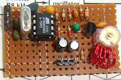
I built mine on a piece of punched phenolic board that had one pad per hole. The holes are in a 0.1 inch grid (2.54 mm). The pads help hold the components tightly to the board, but I am confident that one built on punched phenolic or fiberglass board, or even built Ugly Bug (A.K.A. Dead Bug) or Manhattan style would work just as well. Just make sure that the parts in the transmitter are mounted solidly to help with frequency stability and to reduce microphones.
I used a socket for the micro controller. This because I used a programing adapter that plugged into the socket for the purpose of programming the controllers, and also to let me change the controllers to verify that the other controllers would work. You do not need a socket, but it might give some peace of mind and some forgiveness of mistakes.
Testing and Tuning
If you use a socket for the controller, do not put the controller into the socket until you have verified that the power supply is wired properly. Apply unregulated power to the input of the 78L05 and measure pin 8 of the micro controller. It should be + 5 volts. Verify that pin 4 of the micro controller is grounded.
Tune a nearby FM radio receiver to a quiet spot on the dial, where you would like the transmitter to reside.
Tune C6 to the center of its range and touch L1 with your fingers. If you heard a signal go swishing though the band pass of your FM receiver, it means that the transmitter is tuned at a frequency higher than that which the FM receiver is tuned to. If you did not hear the signal, then stretch the coil lengthwise SLIGHTLY.
At some point, between the effects of stretching the coil and touching it with your fingers, you should be able to bring the transmitter frequency to be very close to that which the receiver is tuned to. At this point, you should be able to use C6 to fine tune the oscillator to the right frequency
After you get the transmitter tuned in, Verify that the transmitter is transmitting at the frequency that your radio is tuned to, and not to an image frequency. Do this by bringing your finger close to L1. When you do this, the frequency will shift. If the transmitter shifts to a lower frequency on your radio dial, then the transmitter is tuned to where you think it is. If the transmitter seems to shift up in frequency, then you are looking at an image and need to re-tune the transmitter.
The procedure above might be tricky, and often requires some finesse. Be patient, it will pay off.
It might be handy to have an un-tuned field strength meter at hand, just to be able to determine if the transmitter is oscillating at all. I relied upon one several times during this project. Here are a some filed strength indicator projects on this site:
Broadband RF Field Strength Probe using Atmel AT90S1200A AVR controller <= This one uses a micro controller to zero the circuit.
A Simple Field Strength Indicator <= This one does not require a micro controller.
Digital RF Field Strength Indicator with LED display using Atmel AT90S2313 AVR Processor <= This is the one I used on this project.
A Field Strength Meter Using A Biased Schottky Detector <= This is a newer design, which is quite sensitive.
The L and R designations on the audio connector are, to my knowledge correct.
Thoughts on Possible Improvements
First off, one might consider adding ESD protection to the audio inputs.
Filters with sharp 10 to 15 kHz audio cutoff on the Left and Right audio channels might help with some audio sources. This would prevent signals that might be in the audio from beating with the 19 khz pilot signal.
Pre-empahsis, a 6 db per octave boost at about 3 kHz on the Left and Right audio channels will compensate for the de-empahsis rolloff in commercial receivers. North American receivers expect one frequency, the rest of the world, something slightly different. You might be able to achieve a similar effect with a graphic equalizer ahead of the transmitter. Using an equalizer in the receiver will restore the frequency response, but will not improve your high frequency signal to noise ratio as pre emphasis was intended.
Printed Circuit Board Design
Jeff attached a clip lead to the coil on his transmitter in order to increase the range a little bit. Note that the inductor is a sufficient antenna for most uses and the extra antenna is not recommended. He has come up with a pretty nice printed circuit board design for this simple FM Stereo Transmitter. Jeff layout accommodates 8 pin AVR controllers. The layout is intended to accept resistors mounted vertically, so you have some flexibility in that you can use any size from 1/8 up to about 1/2 watt sizes.
This layout only requires three jumpers in order to make a single-sided board.
As for the dots per inch, Jeff wrote Opening the file up with Microsoft paint and printing out the image gives 7.5 mm from the center of pin 1 to the center of pin 4. Its a good idea to verify the dot pitch in your own system (As an example, I use a Macintosh, so the dots per inch would probably need to be adjusted.) When everything is scaled properly, the distance between centers on U1, the 8 pin dual inline package, should be 0.1 inches (2.54 mm).
Downloads
Several different AVRs are directly supported. Note: The AT90S2323 and AT90S2313 are no longer manufactured, but the ATTINY parts are still in production.
The eight pin devices, AT90S2323, ATTINY12, and ATTINY25 use the following output pins:
Left =>
Port B bit 2; Right => Port B bit 0; 19 kHz subcarrier => Port B
bit 1, as shown in the schematic.
AVR Studio 4.x assembler source file for ATTINY12
sttn12.asm
AVR Studio 4.x assembler hex file for ATTINY12
sttn12.hex
AVR Studio 4.x assembler source file for ATTINY25
sttn25.asm
AVR Studio 4.x assembler hex file for ATTINY25
sttn25.hex
AVR Studio 4.x assembler source file for AT90S2323
st2323.asm
AVR Studio 4.x assembler hex file for AT90S2323
st2323.hex
The twenty pin devices, AT90S2313 and ATTINY2313 use the following output pins:
Left =>
Port D bit 6 (pin 11) ; Right => Port D bit 4 (pin 8); 19 kHz
subcarrier => Port D bit 5 (Pin 9).
AVR Studio 4.x assembler source file for ATTINY2313 and AT90S2313
st2313v070419b.asm
AVR Studio 4.x assembler hex file for ATTINY2313 and AT90S231
st2313v070419b.hex