|
Accurate LC
Meter Part's List:
|
1x 16x2 LCD Display with Green / Blue Backlight
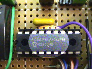
1x PIC16F628A Programmed Microcontroller
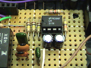
1x LM311 IC
1x Accurate LC Meter PCB with red solder mask
1x Enclosure
1x Gold Plated Machined 18 DIP IC Socket
1x Gold Plated Machined 8 DIP IC Socket
1x L/C Pushbutton Switch with Black Cap
1x Tactile momentary reset switch with Black Cap
1x Gold Plated 16-PIN LCD Female Header
1x Gold Plated 16-PIN LCD Male Header
1x Gold Plated 2-PIN Header
2x Gold Plated 1-PIN Header
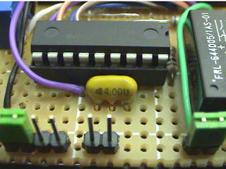
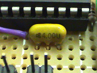
1x 4.000 MHz Crystal
1x High Precision 82uH Inductor
1x 5V Ceramic Reed Relay
1x LM7805 Regulator
1x 10K LCD Contrast Trimmer
2x 1000pF High Precision WIMA Capacitor
1x 100nF High Quality WIMA Capacitor
2x 10pF High Stability Capacitor
2x 10uF Panasonic Capacitor
1x 33 1% Metal Film Resistor
1x 100 1% Metal Film Resistor
1x 1K 1% Metal Film Resistor
2x 6.8K 1% Metal Film Resistor
1x 47K 1% Metal Film Resistor
3x 100K 1% Metal Film Resistor
|
|
|
|
|
Accurate LC
Meter's Technical Specifications:
|
|
Voltage Supply:
6 - 16V
Accuracy: 1%
Full Automatic Ranging
Inductance Resolution: 10nH
Capacitance Resolution: 0.1pF
LC Meter's Inductance Measurement
Ranges:
- 10nH - 1000nH
- 1uH - 1000uH
- 1mH - 100mH
LC Meter's Capacitance Measurement
Ranges:
- 0.1pF - 1000pF
- 1nF - 900nF |
|
|
|
About
Accurate LC Meter
| |
This is one of the most accurate
and simplest LC inductance / capacitance Meters
that one can find, yet one that you can easily build
yourself. This LC Meter allows to measure incredibly
small inductances starting from 10nH to 1000nH,
1uH to 1000uH, 1mH to 100mH and capacitance from
0.1pF up to 900nF. LC Meter's circuit uses an auto
ranging system so that way you do not need to spend
time selecting ranges manually. Another neat function
is reset switch that will reset
the initial inductance / capacitance, making sure
that the final readings of the LC Meter are as accurate
as possible.
|
Special Edition Accurate LC Meter Kit
| |
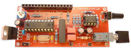
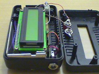
Special Edition LC Meter Kit includes top notch high precision components that are only found in premium quality kits. It includes high quality double-sided printed circuit board (PCB) with red solder mask and pre-soldered tracks for easier soldering, LCD display with yellow-green LED backlight, programmed PIC16F628A microcontroller chip, high precision capacitors and inductor, 1% Metal Film resistors, Machined IC Sockets, gold plated header pins, LCD header connectors and all the other components that are needed to build a premium quality kit. Thanks to the use of LCD connectors LCD display can be detached from the main PCB board at any time even after the kit has been assembled. Special Edition Accurate LC Meter is designed for professionals that require unprecedented measurement accuracy and offers great value at low cost.
|
How does LC Meter Work?
| |
To be able to determine the
value of an unknown inductor / capacitor we can
use the frequency formula given below.
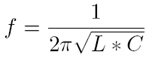
Note that there are three
variables that we can work with; f, L and C (f represents
a frequency, L inductance and C capacitance). If
we know the values of the two variables we may calculate
the value of the third variable.
Lets say we want to determine the value of an unknown
inductor with X inductance. We plug X inductance
into the formula and we also use value of a known
capacitor. Using this data we can calculate the
frequency. Once we know the frequency we can use
the power of the algebra and rewrite the above formula
to solve for L (inductance). This time we will use
the calculated frequency and a value of a known
capacitor to calculate the inductance.
Isn't this amazing? We just calculated the value
of unknown inductor, and we may use the same technique
to solve for the unknown capacitance and even frequency.
|
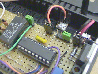
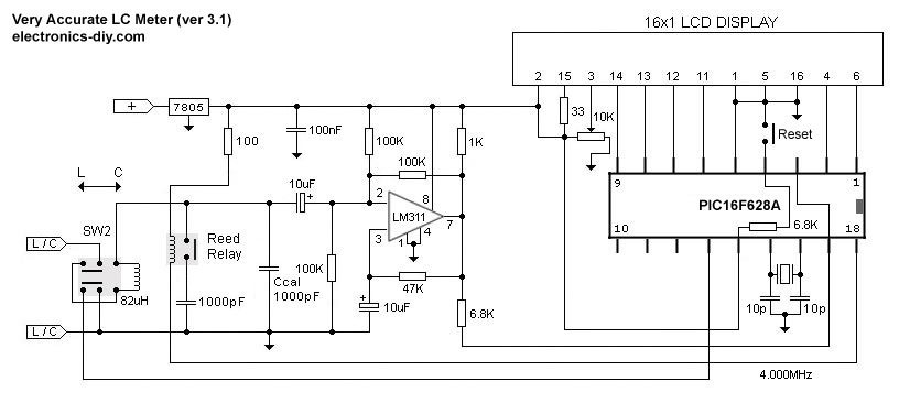
Applying the Theory to LC Meter's Hardware
| |
Now let's use the above theory
and apply it to electronics. The LC Meter uses a
popular LM311 IC that that functions as a frequency
generator and this is exactly what we need. If we
want to calculate the value of an unknown inductor
we use a known Ccal 1000pF capacitor and the value
of an unknown inductor. LM311 will generate a frequency
that we can measure with a frequency meter. Once
we have this information we can use the frequency
formula to calculate the inductance.
The same thing can be done for calculating the value
of a unknown capacitor. This time we don't know
the value a capacitor so instead we use the value
of a known inductor to calculate the frequency.
Once we have that information we apply the formula
to determine the capacitance.
All this sounds great, however if we want to determine
the value of a lot of inductors / capacitors then
this may become a very time consuming process. Sure,
we can write a computer program to do all these
calculations, but what if we don't have an access
to a computer or a frequency meter?
That's were PIC16F628A microcontroller comes handy. PIC16F628A
is like a small computer that can execute HEX programs
that are written using an assembly language. PIC16F628A
is a very flexible microcontroller because it has PINs
which can be configured as inputs and outputs. Besides
that, PIC16F628A IC requires very minimal number
of external components like 4.000MHz crystal / resonator
and a few resistors. Before PIC16F628A microcontroller
can be used it has to be programmed with a HEX code which has
to be sent from the computer. All Accurate LC Meter kits already come with microcontroller that is already programmed and ready to be used.
In the next step we use the frequency generated
by LM311 IC and pass it on to PIC 16F628A's PIN 17.
We designate this PIN as an input, as well as all
other PINs that are directly connected to switches. User can use these inputs to tell the
microcontroller to execute specified set of instructions
or perform calculations.
Once the microcontroller will calculate the unknown inductance
or capacitance it will use PINs that are designated
as outputs and pass the results onto the 16 character
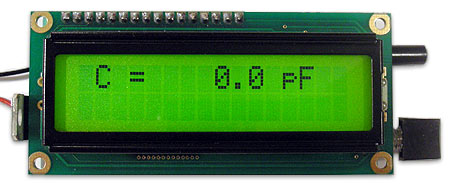
green backlighted LCD display.
|
LC
Meter's Switches
| |
Reset Switch - Resets capacitance / inductance readings
SW2 Switch - Capacitance / Inductance switch
Grounding PIC16F628A PIN12 displays the initial frequency of the LM311
oscillator which should be around 550KHz. This is usefull for testing LM311 oscillator.
|
Character
LCD Display Connections
| |
Most of the character LCD displays have 14 or 16 PINs.
The displays that do have a backlight have 16 PINs
and displays that do not have a backlight have 14
PINs. The PINs that are highlighted in green
in the table below are the ones that PIC16F628A uses
to pass the output information
represented in bits (0/1).
|
PIN |
Symbol |
Function |
States |
|
1 |
VSS |
GND |
- |
|
2 |
VDD |
VCC +5V |
+ |
|
3 |
VO |
Contrast
Adjustment |
+/- |
|
4 |
RS |
Register
Select |
H/L |
|
5 |
R/W |
Read / Write |
H/L |
|
6 |
E |
Enable Signal |
H/L |
|
7 |
DB0 |
Data Bit
0 |
H/L |
|
8 |
DB1 |
Data Bit
1 |
H/L |
|
9 |
DB2 |
Data Bit
2 |
H/L |
|
10 |
DB3 |
Data Bit
3 |
H/L |
|
11 |
DB4 |
Data Bit
4 |
H/L |
|
12 |
DB5 |
Data Bit
5 |
H/L |
|
13 |
DB6 |
Data Bit
6 |
H/L |
|
14 |
DB7 |
Data Bit
7 |
H/L |
|
15 |
|
LED Backlight
VCC +5V |
+ |
|
16 |
|
LED Backlight
GND |
- |
|
|
 |
 |
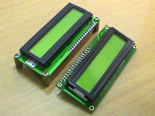
16x1 and 16x2 LCD modules
with backlight (front) |
both LCDs can be used
interchangeably |
 |
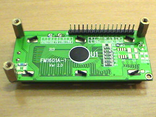 |
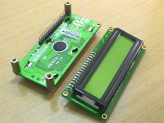
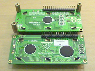
LCD modules (back) |
16x1 LCD with pcb standoffs
and header pins |
|
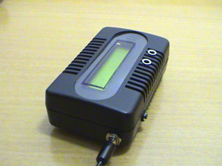
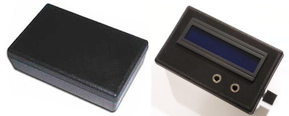
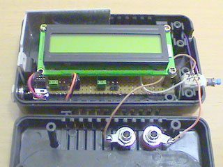
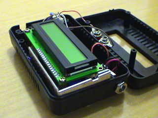
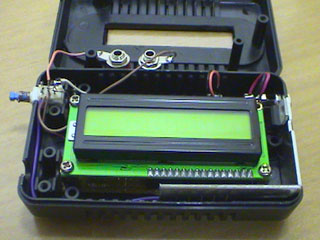
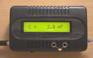
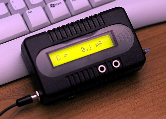
LC
Meter's Enclosure (4"x2.5"x1")
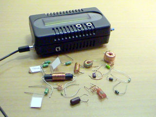
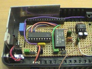
LC
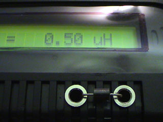
Meter's Early Prototype
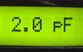
Measuring
2pF Capacitor
| |
 |
 |
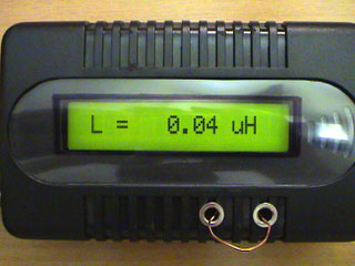
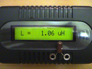
40nH - small piece of
magnet wire |
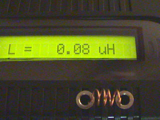
80nH - 4 turns of magnet
wire |
 |
 |
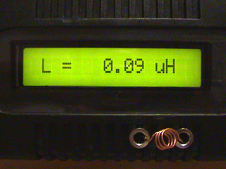
90nH coil used in FM
transmitter |
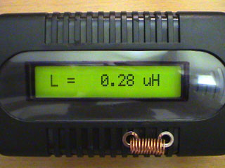
280nH - 10 turns of
magnet wire |
 |
 |
500nH wire through choke |
1uH VK choke |
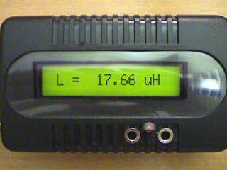 |
 |
small RF toroid, 5 turns |
medium toroid |
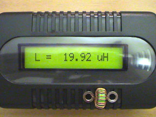
 |
 |
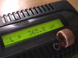
365uH |
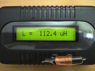
100uH choke |
 |
 |
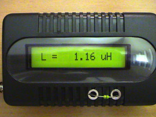
1uH inductor |
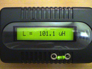
100uH inductor |
 |
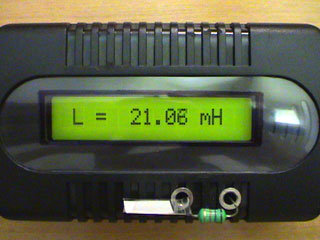 |
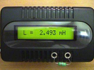
2.2mH inductor |
18mH inductor |
Final
Recommendations
| |
1000pF Ccal is used
as a calibration capacitor and must be a high quality capacitor with tight tolerance.
Cables between LM311 and input terminals must be as short as possible to keep
the stray capacitance to minimum and ensure
the highest accuracy. Also, reed relay must be used because
the current passed from PIC16F628A is very
small. Reed relays require very minimal
amount of current to be switched. LM7805 voltage regulator has to be used to protect
the LCD display and microcontroller. If LM7805 regulator is not used and
higher voltage than 5.5V is accidentally applied LCD and microcontroller will be damaged.
|
Accurate LC Meter Kits
| |
If you are building
the above LC Meter and have trouble finding
some of the components, we are distributing
the following components and a premium quality kits in Electronics-DIY
Store.
|
Related Links
|
|
|
|
| |
Accurate LC Meter
Build your own Accurate LC Meter (Capacitance Inductance Meter) and start making your own coils and inductors. This LC Meter allows to measure incredibly small inductances making it perfect tool for making all types of RF coils and inductors. LC Meter can measure inductances starting from 10nH - 1000nH, 1uH - 1000uH, 1mH - 100mH and capacitances from 0.1pF up to 900nF. The circuit includes an auto ranging as well as reset switch and produces very accurate and stable readings. |
|
PIC Volt Ampere Meter
Volt Ampere Meter measures voltage of 0-70V or 0-500V with 100mV resolution and current consumption 0-10A or more with 10mA resolution. The meter is a perfect addition to any power supply, battery chargers and other electronic projects where voltage and current must be monitored. The meter uses PIC16F876A microcontroller with 16x2 backlighted LCD. |
|
|
|
60MHz Frequency Meter / Counter
Frequency Meter / Counter measures frequency from 10Hz to 60MHz with 10Hz resolution. It is a very useful bench test equipment for testing and finding out the frequency of various devices with unknown frequency such as oscillators, radio receivers, transmitters, function generators, crystals, etc. |
|
1Hz - 2MHz XR2206 Function Generator
1Hz - 2MHz XR2206 Function Generator produces high quality sine, square and triangle waveforms of high-stability and accuracy. The output waveforms can be both amplitude and frequency modulated. Output of 1Hz - 2MHz XR2206 Function Generator can be connected directly to 60MHz Counter for setting precise frequency output. |
|
|
|
BA1404 HI-FI Stereo FM Transmitter
Be "On Air" with your own radio station! BA1404 HI-FI Stereo FM Transmitter broadcasts high quality stereo signal in 88MHz - 108MHz FM band. It can be connected to any type of stereo audio source such as iPod, Computer, Laptop, CD Player, Walkman, Television, Satellite Receiver, Tape Deck or other stereo system to transmit stereo sound with excellent clarity throughout your home, office, yard or camp ground. |
|
USB IO Board
USB IO Board is a tiny spectacular little development board / parallel port replacement featuring PIC18F2455/PIC18F2550 microcontroller. USB IO Board is compatible with Windows / Mac OSX / Linux computers. When attached to Windows IO board will show up as RS232 COM port. You can control 16 individual microcontroller I/O pins by sending simple serial commands. USB IO Board is self-powered by USB port and can provide up to 500mA for electronic projects. USB IO Board is breadboard compatible. |
|
|
|
|
ESR Meter / Capacitance / Inductance / Transistor Tester Kit
ESR Meter kit is an amazing multimeter that measures ESR values, capacitance (100pF - 20,000uF), inductance, resistance (0.1 Ohm - 20 MOhm), tests many different types of transistors such as NPN, PNP, FETs, MOSFETs, Thyristors, SCRs, Triacs and many types of diodes. It also analyzes transistor's characteristics such as voltage and gain. It is an irreplaceable tool for troubleshooting and repairing electronic equipment by determining performance and health of electrolytic capacitors. Unlike other ESR Meters that only measure ESR value this one measures capacitor's ESR value as well as its capacitance all at the same time. |
|
Audiophile Headphone Amplifier Kit
Audiophile headphone amplifier kit includes high quality audio grade components such as Burr Brown OPA2134 opamp, ALPS volume control potentiometer, Ti TLE2426 rail splitter, Ultra-Low ESR 220uF/25V Panasonic FM filtering capacitors, High quality WIMA input and decoupling capacitors and Vishay Dale resistors. 8-DIP machined IC socket allows to swap OPA2134 with many other dual opamp chips such as OPA2132, OPA2227, OPA2228, dual OPA132, OPA627, etc. Headphone amplifier is small enough to fit in Altoids tin box, and thanks to low power consumption may be supplied from a single 9V battery. |
|
|
|
|
|
Arduino Prototype Kit
Arduino Prototype is a spectacular development board fully compatible with Arduino Pro. It's breadboard compatible so it can be plugged into a breadboard for quick prototyping, and it has VCC & GND power pins available on both sides of PCB. It's small, power efficient, yet customizable through onboard 2 x 7 perfboard that can be used for connecting various sensors and connectors. Arduino Prototype uses all standard through-hole components for easy construction, two of which are hidden underneath IC socket. Board features 28-PIN DIP IC socket, user replaceable ATmega328 microcontroller flashed with Arduino bootloader, 16MHz crystal resonator and a reset switch. It has 14 digital input/output pins (0-13) of which 6 can be used as PWM outputs and 6 analog inputs (A0-A5). Arduino sketches are uploaded through any USB-Serial adapter connected to 6-PIN ICSP female header. Board is supplied by 2-5V voltage and may be powered by a battery such as Lithium Ion cell, two AA cells, external power supply or USB power adapter. |
|
200m 4-Channel 433MHz Wireless RF Remote Control
Having the ability to control various appliances inside or outside of your house wirelessly is a huge convenience, and can make your life much easier and fun. RF remote control provides long range of up to 200m / 650ft and can find many uses for controlling different devices, and it works even through the walls. You can control lights, fans, AC system, computer, printer, amplifier, robots, garage door, security systems, motor-driven curtains, motorized window blinds, door locks, sprinklers, motorized projection screens and anything else you can think of. |
|
|
|
|
|