|
|
1W Long Range FM Transmitter
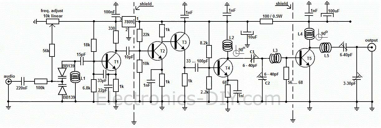
Long range, very stable, harmonic free, FM transmitter circuit which can be used for FM frequencies between 88 and 108 MHz. With good antenna transmitter can cover 5km range. It has a very stable oscillator because it uses LM7809 voltage regulator which is a 9V stabilized power supply for T1 transistor. Frequency adjustment is achieved by using the 10K linear potentiometer. The output power of this long range RF transmitter is around 1W but can be higher if you use transistors like KT920A, BLX65, BLY81, 2N3553, 2SC1970 or 2SC1971.
1W PLL Transmitter with MC145152
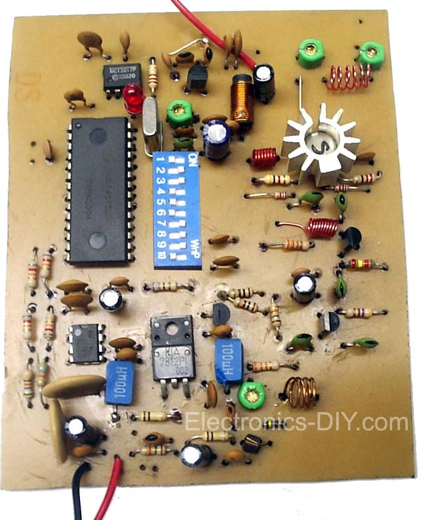
Following 1W PLL transmitter exciter provides stable, low noise operation. Transmitter uses a PLL frequency synthesizer built with MC145152 which covers the FM band in 100kHz steps. The VCO uses MV2109 varicap diode to automatically tune to selected frequency via SW1 dip switch. output stage uses 2N4417 RF power transistor and provides 1W of RF power. With good antenna expected transmission range is 2km. Transmitter may be built on a double sided PCB, with top side copper left mostly undisturbed as a ground plane. The copper is removed only around non-grounded pins. The ground connections can be soldered on the top side, so it's not necessary to have plated-through holes.
1W portable PLL transmitter
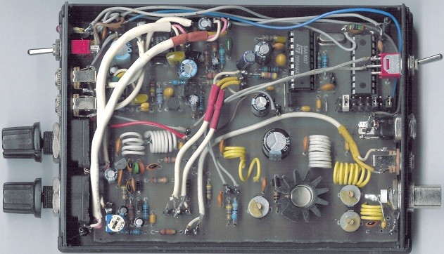
This small FM transmitter includes a limiter, a microphone amplifier and a PLL digital tuning. All the parts are placed on one circuit board. The RF power is switchable between 1W and 0,2W.
The schematic diagram is divided into three parts: RF part (numbered from 1), PLL (numbered from 30) and audio part (numbered from 50).
1W RF Power Amplifier for iPOD Stereo FM transmitters
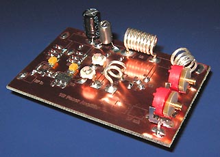
This project explain how you can build and connect a powerful 1W amplifier to your FM transmitters.
A perfect solution for those wishing to listen to their favorite tunes in the car, house, garden,
school, campus, party, you name it....
Why not share your music with every one else in your city!
1Watt AM CW Transmitter for 10 Meterband
In this project, you will make a simple 3-stage low-power broadcast-type circuit, using a crystal oscillator integrated circuit and an a collector modulated AM oscillator with amplifier. You can connect the circuit to the an electred microphone or amplified dynamic microphone. Using an electred microphone is shown (in gray) in the diagram below. (no amplified dynamic microphone has a to low output voltage to work. at least 100mv is needed). You could also add a LF preamp stage of one transistor to allow connecting a dynamic microphone directly.
You'll see that you can receive the signal through the air with almost any AM radio receiver. Although the circuits used in radio stations for AM receiving are far more complicated, this nevertheless gives a basic idea of the concept behind a principle transmitter. Plus it is a lot of fun when you actually have it working!
Remember that transmitting on the 10 meter band you'll need a valid radioamateur license!!
A wide range of different circuits have been used for AM, but one of the simplest circuits uses collector modulation applied via (for example) a transformer, while it is perfectly possible to create good designs using solid-state electronics as I applied here (T1 BC557).
The transmitter is build as a Colpitts Oscillator with a BSX20 transistor. HF-output of the oscillator is approx. 50 mW, depending on the supply voltage of 6 to 15 Volts. This is amplified by the BD135 and brings the power up to approx. 1 watt @ 12volts. The transmit frequency is stabilized with the 28Mhz crystal. A slight detuning of approx 1kc is possible when using a 120pF trimmer capacitor for C8. The oscillator signal is taken from the collector of T2 and guided to the input of T3 which output is lead via an L-filter and low-pass PII filter circuit cleaning up the signal pretty good and ensuring spectral purity. The oscillator is keyed by T1 and the morse key (S). By keying the morse-key T1 is not been used for modulation and is biased, hence lets T2 freely oscillate.
2 Watt FM Transmitter
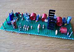
This 2 Watt FM transmitter will provide 10km range in good weather conditions. Use dipole antenna for maximum range. Transmitter can be tuned between 88-108 MHz with c5. BB204 could be replaced with conventional led (big) with reverse bias (no light given in correct polarity). 9v power for 2km transmission with good sound quality and up to 18v for 10km range. 2N3553 RF transistors may be replaced with 2N4427 or 2N3866.
2-5 Km Long Range FM Transmitter
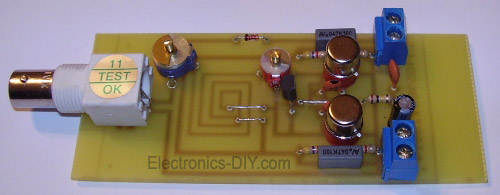
The proposed long range transmitter circuit really is very steady, harmonic free design which you can use with standard fm frequencies between 88 and 108 MHz.
This will likely encompass 5km spectrum (long range). It includes an extremely consistent oscillator for the reason that you employ LM7809 stabilizer that is a 9V stabilized power source for T1 transistor and for frequency realignment that may be reached by means of the 10K linear potentiometer. The output strength of this long range rf transmitter is approximately 1W. Transistor T1 is employed as an oscillator stage to present a small power steady frequency. To fine-tune the freq. apply the 10k linear potentiometer this way: should you moderate, in the direction of ground, the freq. would probably decrease but when you fine-tune it in direction of + it would climb. Essentially the potentiometer is needed just as a flexible power source for the a pair of MV2019 varicap diodes. Both of these diodes function as a changeable capacitor whilst you regulate the pot. By tweaking the diode capacitance the L1 + diodes circuit renders a resonance circuit for T1. Feel free to employ transistors similar to BF199, BF214 however be careful not to use BCs. At this point you don’t receive yet the long range fm wireless transmitter due to the fact that the electric power is fairly reduced, a maximum of 0.5 mW.

200mW FM Broadcast Transmitter
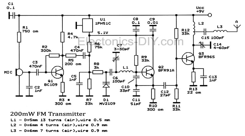
A simple 200mW FM Transmitter circuit which covers frequencies from 88 to 108 MHz. It is built with 3 transistors: BC109, BFR91A and BFR96S. It is quite stable and the output power is around 200mW.
The first stage of transmitter is a mic amplifier but if you connect this radio transmitter directly to an audio source you can remove this stage and connect the audio signal to R5.
U1, 1PH51C can be replaced with LM7805. You must use a stabilized power source for oscillator stage to prevent frequency variation. You can remove C7 and use a linear potentiometer instead of R6 with the median connector to C4, one pin to ground and the other one to +. FM Transmitter uses MV2109 varicap diode and C7 for frequency tuning.
20W FM Amplifier
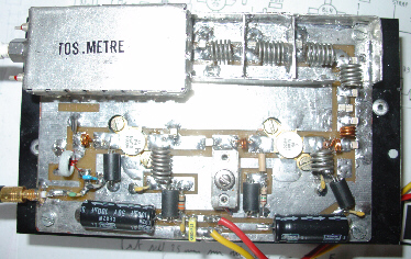
This Power amplifier is equiped with two Philips bipolar transistors : the BLV10 & BLW87.
As lots of FM amplifier design, the RF transistors are in a class C bias. The FM amplifier has a 21 dB gain with a 55 to 65% efficiency.
250mW FM Transmitter Amplifier
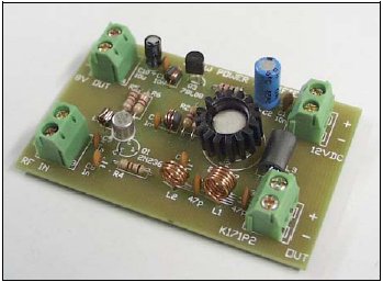
This project is a simple 2-transistor VHF power amplifier, with about 16dB gain, and requires no tuning or alignment procedures. Wideband techniques have been used in the design and the circuit is equipped with a "lowpass" filter to ensure good output spectral purity. The project has been designed for assembly on a single-sided printed circuit board. The circuit is specifically designed to amplify the output of 7mW to 10mW WBFM transmitters (wide band) to a final level of 250mW to 300mW.
|
|
|
| |
Accurate LC Meter
Build your own Accurate LC Meter (Capacitance Inductance Meter) and start making your own coils and inductors. This LC Meter allows to measure incredibly small inductances making it perfect tool for making all types of RF coils and inductors. LC Meter can measure inductances starting from 10nH - 1000nH, 1uH - 1000uH, 1mH - 100mH and capacitances from 0.1pF up to 900nF. The circuit includes an auto ranging as well as reset switch and produces very accurate and stable readings. |
|
PIC Volt Ampere Meter
Volt Ampere Meter measures voltage of 0-70V or 0-500V with 100mV resolution and current consumption 0-10A or more with 10mA resolution. The meter is a perfect addition to any power supply, battery chargers and other electronic projects where voltage and current must be monitored. The meter uses PIC16F876A microcontroller with 16x2 backlighted LCD. |
|
|
|
60MHz Frequency Meter / Counter
Frequency Meter / Counter measures frequency from 10Hz to 60MHz with 10Hz resolution. It is a very useful bench test equipment for testing and finding out the frequency of various devices with unknown frequency such as oscillators, radio receivers, transmitters, function generators, crystals, etc. |
|
1Hz - 2MHz XR2206 Function Generator
1Hz - 2MHz XR2206 Function Generator produces high quality sine, square and triangle waveforms of high-stability and accuracy. The output waveforms can be both amplitude and frequency modulated. Output of 1Hz - 2MHz XR2206 Function Generator can be connected directly to 60MHz Counter for setting precise frequency output. |
|
|
|
BA1404 HI-FI Stereo FM Transmitter
Be "On Air" with your own radio station! BA1404 HI-FI Stereo FM Transmitter broadcasts high quality stereo signal in 88MHz - 108MHz FM band. It can be connected to any type of stereo audio source such as iPod, Computer, Laptop, CD Player, Walkman, Television, Satellite Receiver, Tape Deck or other stereo system to transmit stereo sound with excellent clarity throughout your home, office, yard or camp ground. |
|
USB IO Board
USB IO Board is a tiny spectacular little development board / parallel port replacement featuring PIC18F2455/PIC18F2550 microcontroller. USB IO Board is compatible with Windows / Mac OSX / Linux computers. When attached to Windows IO board will show up as RS232 COM port. You can control 16 individual microcontroller I/O pins by sending simple serial commands. USB IO Board is self-powered by USB port and can provide up to 500mA for electronic projects. USB IO Board is breadboard compatible. |
|
|
|
|
ESR Meter / Capacitance / Inductance / Transistor Tester Kit
ESR Meter kit is an amazing multimeter that measures ESR values, capacitance (100pF - 20,000uF), inductance, resistance (0.1 Ohm - 20 MOhm), tests many different types of transistors such as NPN, PNP, FETs, MOSFETs, Thyristors, SCRs, Triacs and many types of diodes. It also analyzes transistor's characteristics such as voltage and gain. It is an irreplaceable tool for troubleshooting and repairing electronic equipment by determining performance and health of electrolytic capacitors. Unlike other ESR Meters that only measure ESR value this one measures capacitor's ESR value as well as its capacitance all at the same time. |
|
Audiophile Headphone Amplifier Kit
Audiophile headphone amplifier kit includes high quality audio grade components such as Burr Brown OPA2134 opamp, ALPS volume control potentiometer, Ti TLE2426 rail splitter, Ultra-Low ESR 220uF/25V Panasonic FM filtering capacitors, High quality WIMA input and decoupling capacitors and Vishay Dale resistors. 8-DIP machined IC socket allows to swap OPA2134 with many other dual opamp chips such as OPA2132, OPA2227, OPA2228, dual OPA132, OPA627, etc. Headphone amplifier is small enough to fit in Altoids tin box, and thanks to low power consumption may be supplied from a single 9V battery. |
|
|
|
|
|
Arduino Prototype Kit
Arduino Prototype is a spectacular development board fully compatible with Arduino Pro. It's breadboard compatible so it can be plugged into a breadboard for quick prototyping, and it has VCC & GND power pins available on both sides of PCB. It's small, power efficient, yet customizable through onboard 2 x 7 perfboard that can be used for connecting various sensors and connectors. Arduino Prototype uses all standard through-hole components for easy construction, two of which are hidden underneath IC socket. Board features 28-PIN DIP IC socket, user replaceable ATmega328 microcontroller flashed with Arduino bootloader, 16MHz crystal resonator and a reset switch. It has 14 digital input/output pins (0-13) of which 6 can be used as PWM outputs and 6 analog inputs (A0-A5). Arduino sketches are uploaded through any USB-Serial adapter connected to 6-PIN ICSP female header. Board is supplied by 2-5V voltage and may be powered by a battery such as Lithium Ion cell, two AA cells, external power supply or USB power adapter. |
|
200m 4-Channel 433MHz Wireless RF Remote Control
Having the ability to control various appliances inside or outside of your house wirelessly is a huge convenience, and can make your life much easier and fun. RF remote control provides long range of up to 200m / 650ft and can find many uses for controlling different devices, and it works even through the walls. You can control lights, fans, AC system, computer, printer, amplifier, robots, garage door, security systems, motor-driven curtains, motorized window blinds, door locks, sprinklers, motorized projection screens and anything else you can think of. |
|
|
|
|